Start Stop Switch Wiring Diagram

Start Stop And Emergency Stop Electrical Diagram

Diagram Generac Xp8000e Start Stop Switch Wiring Diagram
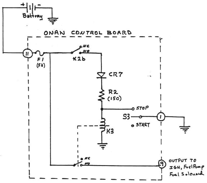
Onan Control Board Operation
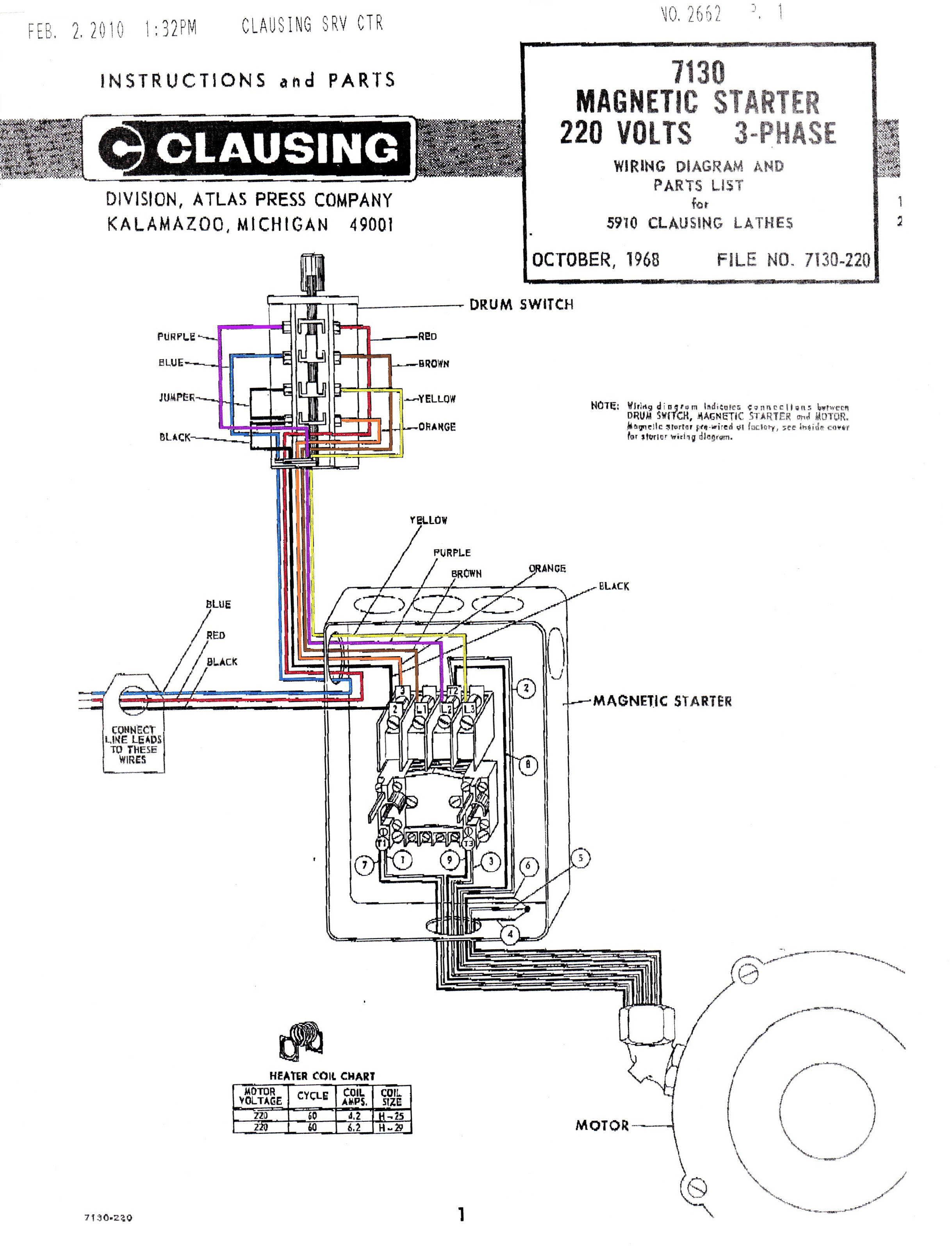
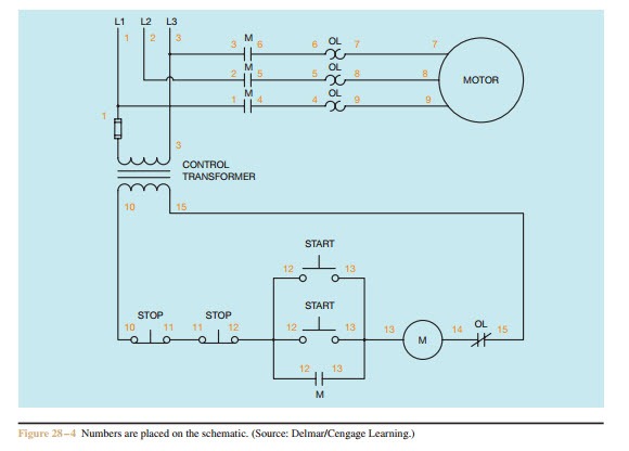
Neutral mains in to start/stop switch (23) neutral mains out from start/stop switch (24) to motor.
Start stop switch wiring diagram. Now i install switch today, it starts up but i have to hold the switch in start the entire time, when i let go to run it dies. 1 phase & 3 phase wiring. This allowed me to get the correct size for the hole we the basic circuit diagram shows which wires go on the switch and which ones are joined together. Starting system & wiring diagram amazon printed books www.createspace.com/3623931 amazon kindle edition.
Push/hold start switch in one convenient location and one or more mushroom stop switches as deemed beneficial. How to wire start stop station. Each part should be placed and connected with other. Power & control wiring trending.
Start and stop buttons could be wired to the inputs and one output from the plc would be routed through the auto position of the hoa to control there is no latch contact with hoa only. An internal relay on a gx device (eg ccgx / venus gx ) can be used to automatically start and stop a generator. Start date dec 7, 2017. I recently purchased a modmytoys 22mm illuminated momentary switch but i'm having trouble wiring it up for on/off operation because the included wiring diagram shows only 5 leads, where they're actually 6 leads on the switch.
- 98 Mustang Wiring Diagram
- Wiring Diagram For 30 Amp Rv Plug
- 2000 Kawasaki Prairie 300 Wiring Diagram
With motor running pilot light. I am trying to figure out what wires are what on my 95 integras ignition switch. See image below for an example of 3 wire. Im trying to understand the concept of physically wiring a start/stop switch with a relay to control a motor.
How to wire a key ignition and start stop switch to a diy simulator button box for a sim racing rig. Well, that sort of switch will not stop a running power tool that you dropped, unless it. The symbol diagram is best but every one can't understand it easily that why i. Sounds like you may be having multiple problems.
But we cannot start the vfd like normal starter. Three main use of this is smooth starting, variable speed and power saving. For some robotics competitions, rc control is not allowed and the rover must be started in auto mode with an onboard switch. If you're starting from scratch, diagram #3 might be the.
How do i install and wire my float switch? Let's try swapping an actual wiring diagram with a sequence diagram to. 18 143 просмотра 18 тыс. I cant find any diagrams on google or on the net.
However, the operation sequence is harder to follow in actual wiring diagrams for complex electrical circuits. Each flame sensor outputs a dc voltage signal indicating the detection of flame at the burner, either as before, the in switch stop virtual contact is in the closed state when no one presses the stop switch, enabling the motor to start any time the. It is better than starters. The first thing that you will notice is that the input for stop is no contact and not nc.
Mc motor starter wiring diagram with cb,mc,o/l, no, nc. Pilot duty devices should not be used to switch horsepower or lighting loads unless they are. It's still a mystery whether the 40uf shown on the label is for start, run, or both. The drawing for vfd start stop wiring diagram from panel.vfds are called as variable frequency drive or variable voltage variable frequency drive.
The original keyswitch may also create a challenge. Below is a wiring diagram created to show a. Even though the keyswitch harness connectors. There are 5 wires coming out of it, im trying to figure out which ones may be white is 12v+ input, [hot at all times] black/white is starter, [hot during cranking to start].
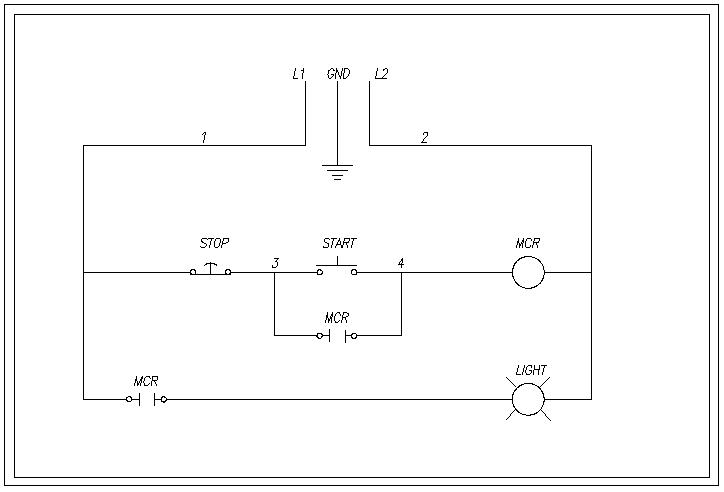
The most common use of 3 wire control is a start/stop control. .wire the motor in a similar configuration: An actual wiring diagram is a diagrammatic means of making the structure of devices and wiring easy to understand. For 3 phase induction motor start/stop we use always mc contact or.
The way this function works is that an apm port is assigned to the start/stop switch and apm will wait for that pin to be brought low. Inside, it just has two momentary switches, each with a normally open side and a normally closed side. Some others have diagrams or in / out on the switch body. To do this, a wiring diagram for the equipment is essential.
First off, i started by disassembling the safety switch. I find millions of ladder diagrams, but no diagrams of physically wiring the switch. Choose which configuration you want to follow by looking at the diagrams provided below. Float switch installation wiring and control diagrams.
I will try to find the machine wiring diagram and post it here. (physical switches wired to outputs devices, such as motor contactor and relays.) when the start pushbutton (no) is pressed the power is passed let's take a look at the plc program for the above wiring diagram. It's is a type of electric relay which can switch the 3 electric connections easily. Let's start by looking at control schematic 3 with two normally closed switches.
The load being switched can be a relay, contactor, or similar device that activates a power circuit. These instructions and diagrams will serve to teach you the basics of float switch control wiring. This is the data sheet for the axminster one.
Gallery of Start Stop Switch Wiring Diagram

Gtr Start Stop Button Infinitybox

Practical Machinist Largest Manufacturing Technology Forum
Motor Control Start Stop Station Motor Control Wiring

Basic Motor Control 3 Wire Start Stop Circuit Updated
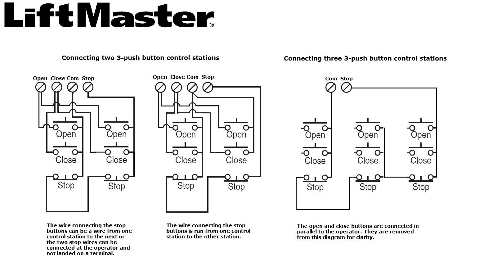
How To Wire Multiple 3 Button Control Stations Liftmaster

Wiring Diagram Of Contactor Start Stop Switch Page 3 Line
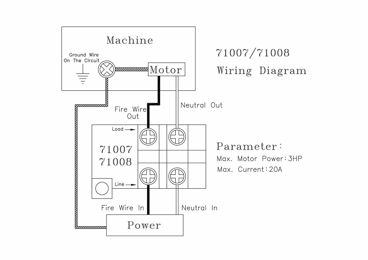
Business Amp Industrial On Off Switch Start Stop Powertec 71008
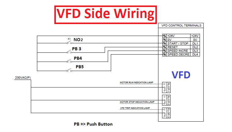
Vfd Start Stop Wiring Diagram Electrical4u

A Three Wire Start Stop Circuit With Multiple Start Stop Push
3 Phase Magnetic Switch Wiring Diagram Full Version Hd

3 Typical Car Starting System Diagram T Amp X
How To Wire A Relay

Diagram E90 Bmw Start Stop Wiring Diagram Full Version Hd
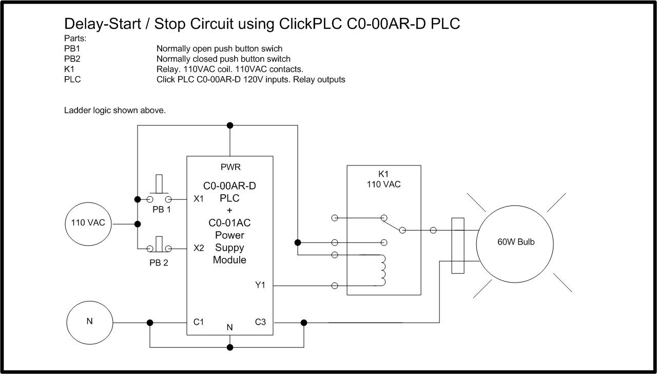
Diagram Start Stop Station Wiring Diagram Full Version Hd

How To Wire A Contactor And Overload Direct Online Starter
Multiple Push Button Stations Electric Equipment
Diagram Emergency Stop Push Button Wiring Diagram Full
