Rpm Meter Wiring Diagram

Diagram Wiring Diagram Rpm Meter Full Version Hd Quality Rpm

Diagram Auto Meter Tach Wiring Diagram For 5160 Full Version

Eb8 4 Wire Tachometer Wiring Diagram Wiring Library
Calibration calibrate the meter before installation using a pulse generator.
Rpm meter wiring diagram. Easy to build, 3d printed and homemade rpm meter/tachometer with arduino. A b b 2 pg card and pulse generator b. 5 kces college of engineering ,jalgaon. From the electric pole to wire comes first one is phase and second one is neutral.
There are 31 suppliers who sells rpm meter wiring on alibaba.com, mainly located in asia. The rev speed meter requires both the instruction manual and the wiring diagram for proper when connecting the ig power, engine rpm, ground, vehicle speed signal wires to the ecu, be. I have a red and blue led version. So we have to use a sensor to keep track of this d…
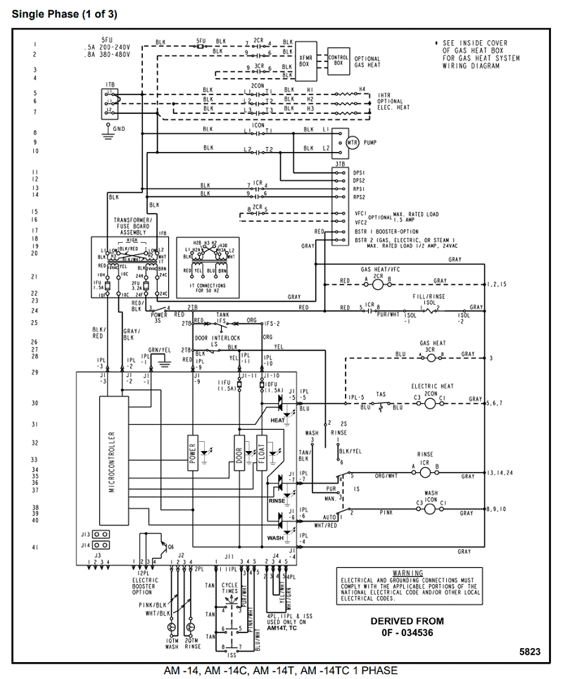
Our system stores wiring diagram rpm. A , output 12v dc vp dcm e. Single phase wiring diagram for home. I am trying to build a cadence counter for an on bike computer.
- Yamaha Bear Tracker 250 Wiring Diagram
- Troy Bilt 2700 Pressure Washer Carburetor Diagram
- 99 Mercury Cougar Fuse Box Diagram
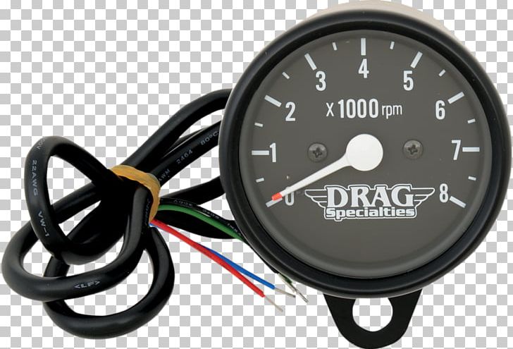
Rpm (round per minute) is a number that shows the number of turns of a system in 1 minute. I am triing to build a car rpm meter and i have no idea where to start and is it even posible to do it whitouth distroing the car. Usually used as a pointer to engine rotation on a motorized vehicle, making it easier to regulate power and fuel. With volt meter set on ac scale, both leads touching alternator pins meter should read 16 to 20 volts ac for every 1000 rpm's 1989 and later.
The circuit is easy and based on a ir led and phototransistor. So we have to measure how many times a particular point on the rotor undergoes a full rotation within a minute. Set the generator to the maximum input frequency, 1.5 ms. Tachometers with two or three buttons use an advanced microcontroller circuit to measure engine rpm for increased accuracy and zero pointer flutter at low.
This is the circuit diagram of digital tachometer / digital rpm meter which can be used for cars or motorcycles with 2 and 4 stroke petrol engines with any number of cylinders and contact breaker or electronic ignition systems. Arduino based rpm meter (3d printed case). Rpm meter ka connection vfd se कैसे करते है drive analog outputs playlists: Rpm meter wt3r dc generator 12v pulse generator 5.5kw motor wiring diagram ac motor control 5.5kw 12v generator diagram deltronic 37kw motor wiring diagram text:
Complete wiring diagram of sensors figure out cable routing within the cvt cover and model. Wat colour wire is for the rev counter at the back of instrument cluster on a vw caddy pickup 2005 and what colour wire does it 10. Using an arduino to display on lcd rpm from a pc fan utilisation d'un arduino pour affichage sur lcd des tours par minute d'un ventilateur de pc. Hi guys, in this video i will show you the step by step procedure to install rpm meter on any bike.
Digital rpm meter using arduino. Digital rpm meter using simplest technique for kids. We support all android devices such as samsung download wiring diagram rpm gauge app directly without a google account, no registration, no login required. Basic wiring diagram with rpm meter attached.
Nov 24, 2013, 11:35 pm. Currently rpm meters needed for industrial applications are imported from abroad and are quite expensive. In rpm meter the system counts the rounds of motor.it mean that there is a system that after every completion of round of motor its gives actually when any key of calculator is pressed in practical it shorts circuited two wires.now if we press 1 on. Pdf | an rpm meter is a device to measure the number of revolutions a rotating object makes in a minute.
The top countries of supplier is china, from which the percentage of rpm meter wiring supply is 100% respectively. May be used as a general purpose revolution counter. You can choose the wiring diagram rpm gauge apk version that suits your phone, tablet, tv. If anyone is looking for a simple cheap digital rpm meter suitable for a machine tool, look here:
Single phase electrical meter or single phase energy meter. Digital rpm meter using arduino. Here in our circuit we use this device to convert the analog voltage signal into digital support twi communication using the wire library. A low cost rpm meter can be made using a simple 8 bit microcontroller.
Start date sep 19, 2004. 546 rpm meter wiring products are offered for sale by suppliers on alibaba.com. It is vital for dominant the e wiring. And also tell you what does rpm.
See note on circuit diagram.
Gallery of Rpm Meter Wiring Diagram
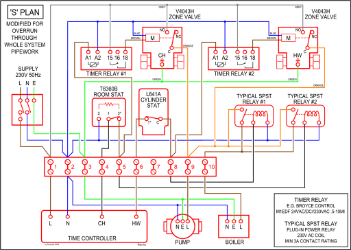
Diagram Auto Gauge Rev Counter Wiring Diagram Full Version

Diagram Wiring Diagram Rpm Vdo Gauges Full Version Hd

17 Quick Car Gauge Wiring Diagram Car Diagram Wiringg

How To Install A Tachometer Onallcylinders
Teleflex Tachometer Wiring Gota Wiring Diagram

Gf 1149 Auto Meter Tach Wiring Diagram For Motorcycle

Diagram Wiring Diagram Tachometer Defi Full Version Hd

Diagram Rpm Gauge Wire Diagram Full Version Hd Quality Wire
Mini Car Tachometer Electrical Wires Amp Cable Wiring Diagram

Diagramme Vdo Rpm Gauge Wiring Diagram Full Version Hd

10 Motorcycle Rpm Wiring Diagram Tachometer Car

Diagram Diagram Rpm Meter For Automobiles Wiring Diagram

Diagram Vdo Tach Wiring Diagram Usa Full Version Hd Quality

Diagram Digital Tachometer Rpm Meter Wiring Diagram Full

Digital Led Rpm Speedometer Tachometer With Hall Senzor
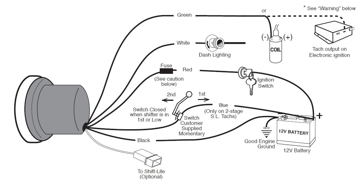
Diagram Aftermarket Rpm Gauge Wiring Diagram Full Version Hd

Installing Moto R Analog Tachometer Techy At Day Blogger
