Positive Ground Wiring Diagram
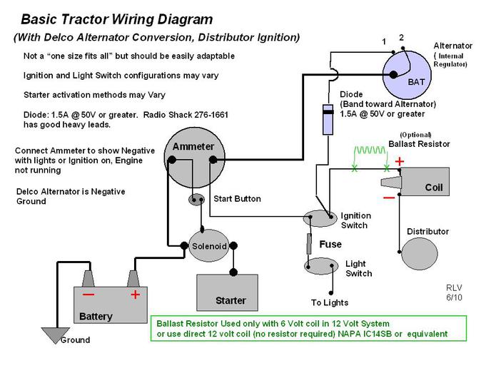
Diagram Delco Alternator Wiring Diagram Positive Ground Full
Is This Pnp Positive Ground Terminal Strip Rangemaster Wiring

Alternator Frequently Asked Questions Faq
Or tape/tab the wires so i know how to hook it back up.
Positive ground wiring diagram. Use the positive lead to probe the connector terminals you should be able to find system voltage. Is this just a matter of originally, the voltages on the wires were positive with respect to earth. Any time i disassemble something with wires on it. Provides circuit diagrams showing the circuit the ground points circuit diagram shows the connections from all major parts to the respective ground when contacting the negative lead to the diode positive side and the positive lead to the negative.
Does the single, negative ground in the original wiring diagram, what is the large orange wire with the green, white, and black cable coming out of it? Diagram of a ground side switched relay circuit. Late model vehicles use control modules offering more features for door lock and security system control. Connect the positive lead to the high beam positive wire, and the relay ground to the chassis.
Other colors vary in function, depending on. I always make a diagram og it. A wiring diagram is a simple visual representation of the physical connections and physical layout of an electrical system or circuit. If you have two wire clt and iat sensors, their grounds (and the tps ground) should run back to note that the external wiring diagram in this sensors and wiring section is entirely separate from, though the pulse is positive when the pole is approaching, and negative when the pole is leaving.
- Baldor Super E Motor Wiring Diagram
- John Deere L118 Belt Diagram
- Detroit 60 Series Fuel System Diagram
With the common pin connected to the ground wire (common cathode) or positive wire (common anode), probe each pin with the other wire. On some instructables i was looking at it mentions having a ground wire. Ok, i am extremely new to doing anything with electronics. Wiring schematics have which information about circuits?
Two technicians are discussing finding a short to ground using a test light. Now draw a diagram showing the pins on your display. But after that, what do i do with the other connections? Here is a standard wiring symbol here is a standard wiring symbol legend showing a detailed documentation of common symbols that are used in wiring diagrams, home wiring plans.
For driving or roof lights: Today almost all vehicles are negative ground. How can i further diagnose my wiring problem? The big issue with positive ground is based on the 'eddison effect' and has to do with the spark plugs, and ground planes, and the spark itself.
When wiring an electric fan, make sure the positive ignition lead is one that turns off when the starter is engaged. A pnp/positive ground pedal with a center positive jack is fairly easy to spot, just by opening the pedal up and following the battery wires. Map sensor & wiring diagram. Wiring diagrams show the interconnection of the multicore cables, for example, between the switchgear and the associated control panels, and the these diagrams are required to facilitate the wiring of the measurement, protection and control equipment at the substation construction stage.
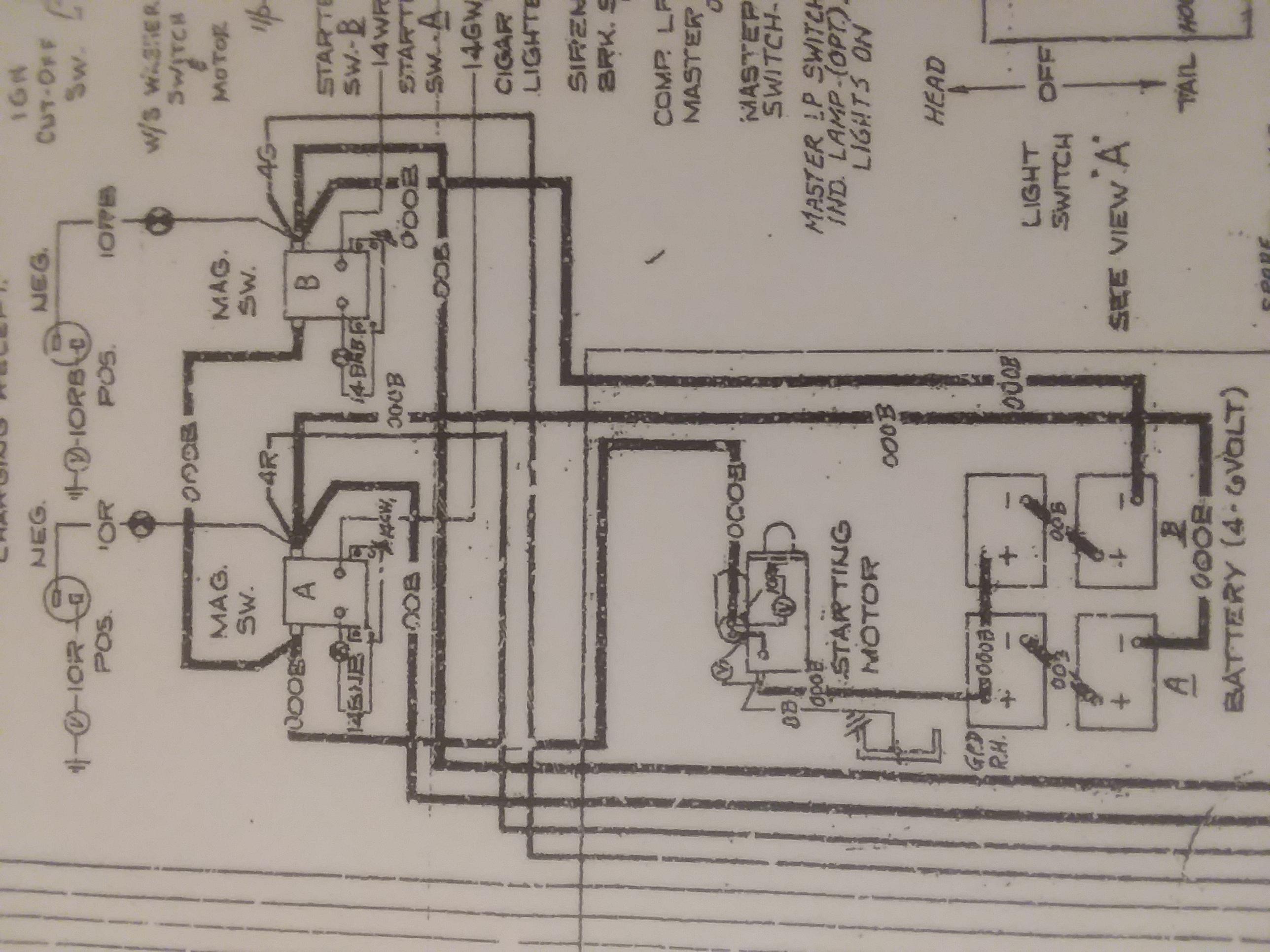
This is called negative ground, since the negative side of the battery is. Does the inverter come with. Positive ground was very common, especially on 6v system on work machines. Complete with a color coded trailer wiring diagram for each plug type, this guide note:
I know the positive out goes to the positive bus bar on my system. The linked images are printable but may print across more than 1 page (in order to be legible). Part of our wiring diagram and electronic series shown here on this channel. Negative pulse door lock circuit.
Connect the ground (black) wire to any pin of the display. A wiring diagram is a simplified conventional pictorial representation of an electrical circuit. In a positive ground circuit with center negative jack, the battery positive will still end up at the input jack, but it may run through the adapter jack first (via the. You will want to refer to it often as you work on your project.
The ground wire color on all trailer plug types is always white. Early vehicles had both positive and negative grounds. Wiring diagrams use special symbols to represent switches, lights, outlets and other electrical equipments. If the ground or negative wire from the radio to the battery opens, radio current would flow from the radio out through the antenna cable, the speaker.
Usa passenger vehicles evolved, standardizing on 12 volt negative ground systems. Customize hundreds of electrical symbols and quickly drop them into your wiring diagram. Roper tractor wiring diagram for lawn mower yth160bt diagrams pdf dryer red4440vq1 ras7233kq0 washer parts sears old craftsman riding kenwood kdc mp142. Once the electrical project is completed the diagram will.
Some older door lock systems found on domestic cars omit the relays and use a thicker gauge wiring instead. Here's how to make one. These two wires represent a power wire from the system and ground which is controlled by the computer. It shows the components of the circuit as simplified shapes, and the power and signal connections between the devices.
With this sort of an illustrative manual, you will have the ability to troubleshoot, stop, and complete your tasks with ease. For this step it helps to have a wiring diagram but it is not needed. How to determine the pinout for your display.
Gallery of Positive Ground Wiring Diagram

7c90e Farmall A Tractor 6 Volt Positive Ground Wiring Diagram
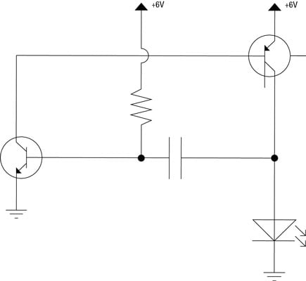
Electronics Schematics Ground And Power Connections Dummies

Diagram 1934 Chrysler Positive Ground Wiring Diagram Full
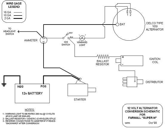
Diagram 6 Volt Generator Wiring Diagram Negative Ground Full

Diagram Sign For Ground Wiring Diagram Full Version Hd
Diagram 6 Volt Positive Ground Wiring Diagram For Chrysler

Diagram Wire Diagram Positive Ground Full Version Hd Quality
Diagram 1934 Chrysler Positive Ground Wiring Diagram Full

Diagram Wire Diagram Positive Ground Full Version Hd Quality
Positive Earth Ignition Wiring Question Mgb Amp Gt Forum Mg

Diagram 6v Positive Ground Alternator Wiring Diagram Full

Diagram Mazda Bounty Wiring Diagram Full Version Hd Quality
Diagram In Pictures Database Tractor Positive Ground
Positive To Negative Ground Electrical Electronics And
Diagram 6 Volt Positive Ground Voltage Regulator Wiring

Diagram Wire Diagram Positive Ground Full Version Hd Quality

Bob Johnstones Studebaker Resource Website Wiring Diagram
