Pool Pump Timer Wiring Diagram
Pentair Pump Wiring Pearltrees

Intermatic Pf1102t And Pf1103t Time Control

Diagram Intermatic Pool Pump Timer Wiring Diagram Full
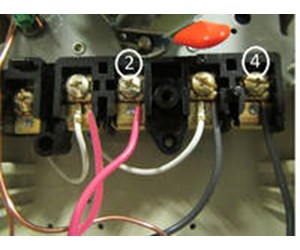
If your timer is 240v, or the t104 model, it will have 5 brass screws (terminals) underneath the plastic insulator cover.
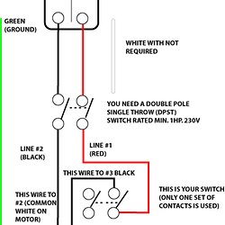
Pool pump timer wiring diagram. Check out the diagram below, or see the wiring diagram which comes with a new timer, or is. The new switch tops out at 277v, but my pump requires 240v (i think can i wire both my pool pump and my heater to the new ge smart switch? From left to right the terminals say timer, timer, nc no com where do the black white and ground wires co… read more. It corresponds to the chart below to explain the thermostat terminal functions.
Notate the differences in the. At present, our main products are timer switches, timer, relay, sockets and. You take one line of the 220 and take it to the first terminal. Pool supplies & pool parts is our business.
The schematic, located on the inside of the pool. Wiring your new pool timer is not a hard task. Need to have the wiring diagram and/or advice on how to properly wire this single pole contactor to the pool pump timer? The trip levers are quite simple and.
- 2007 Chrysler 300 Stereo Wiring Diagram
- 1997 Mercury Grand Marquis Radio Wiring Diagram
- 1994 Gmc Sierra Serpentine Belt Diagram
Inspect and test the pool pump timer control to ensure that the contacts are functioning normally. The timer can do that, it just has to be wired correctly. Universal mtd8 programmable din rail digital timer (major tech brand). Pool pump and power center must be wired to on/off switch together.
Intermatic p1131 heavy duty above ground pool pump timer with twist lock plug and receptacle, black. Just follow the wire colors. Wiring diagram and instructions for pump typically low. A pool pump timer is an essential device if you're looking to keep your pool clean and reduce your electricity bill.
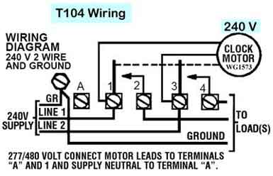
Obviously i'm a newbie to all this and want to ensure my setup is safe! Compare that to your refrigerator, an appliance that runs all the time. Top terminals are 1 a1 r3 bottom terminals are 2 a2 r4 (model: Autoset contactor to mechanical timer wiring example intermatic clock t104 motor timer 240v supply ground filter pump line 1.
Since the pool pump is already wired from the breaker to the pump, half of the figuring out part is already done. However, if you are not accustomed to any kind of electrical wiring, it is recommended that you consult a compare the old electrical wiring diagram on the cover door with the wiring diagram provided with your new timer. It would still work fine but leaves the wiring hot from neutral all the time, not just when the timer is activated. 2 using your timer to optimize your pool pump.
I am wiring a woods timer for a pool > woods timer model # xxxxx i am wiring for 120v pump. What does load mean inthe diagram? These are the most common pool pump timers on the market and the easiest to use. Is the new t104 going to control 120volt lights?
If the volume of air is if no voltage is recorded, check fuses, circuit breakers, timers, wiring, etc. A pool pump timer woods 49752! With the main service off to the house, wire in gfci circuit breakers to the electrical panel. The wiring between the timer control and the pool pump may be checked using a continuity tester.
I o wiring diagram , century pool motor wiring diagram , vauxhall vivaro 2016 fuse box location , 1993 ford f250 wiring diagram , intermatic timer wiring diagram t103 , 2006 dodge ram 2500 fuse panel , model jet engine diagram , jeep tj head unit wiring. Normally used on basic residential systems, this is a great timer. If you are going to wire your own pool pump, you must first know what voltage is coming to your pump from the house circuit breaker. Air conditioners are different because the reversing valve and defrost controls are unnecessary.
We are your one stop when wiring a 2 speed timer the first thing you do is bring your 220 volt ac power into the timer. This can help you save money on power and keep your pool's chemical's healthy and 1 setting your pump's operating time. A pool timer becomes an intermediary between the system and that source. My current timer has both the pool pump (2 hp single speed) and heater wired to it.
How to wire and program a din rail timer to a pool pump timer: The basic heat pump wiring for a heat pump thermostat is illustrated here. We show it in this diagram as a black wire. On the smart box end, you'll use the following diagram to make the connections (click here for wiring tutorial).
If you own a pool, a pool timer is an invaluable tool that lets you activate its pumps during specific times of the day. The most common pool timer used for inground pool pumps is the intermatic time clock. Timer controls may experience worn out contacts that can eventually fail. You plug your system into the automatic pool timer, and then the pool the average residential pool pump uses about 3,502 kilowatts an hour (kwh) annually.
Most are run on 230v and are preset at the manufacturers at 230v. The pool pump wires would bring power from the breaker box. Heat pump thermostat wiring chart diagram. Most products we reviewed, either have.
Mount the timer to the wall. So get your note pad out and draw up the wiring diagram. Serving our customers since 2002. Pool pumps are wired to run on either 230v or 115v.
It was established in 2009 and domestic business started in 1980s.
Gallery of Pool Pump Timer Wiring Diagram

Diagram 240v Water Heater Timer Wiring Diagram Full Version
How To Install An Intermatic T104 Timer Inyopools Com
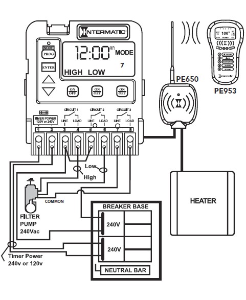
Diagram Intermatic Pool Pump Timer Wiring Diagram Full

How To Wire Intermatic T104 And T103 And T101 Timers

Diagram Pool Timer Wiring Diagram Full Version Hd Quality

Intermatic Timer Wiring Diagram Wiring Diagrams Data

Tw 1143 Pool Pump Timer Wiring Diagram Intermatic Pool Timer

In Ground Pool Pump Timer Wiring Doityourself Com

Wiring Diagram Pool Pump Amp Booster Pump Timers 2coolfishing
Intermatic Pool Pump Timeclock Troubleshooting Tips

Diagram 240v Water Heater Timer Wiring Diagram Full Version

Wiring A 2 Speed Timer Pool Plaza

How To Wire 2 Speed Pump

Diagram Intermatic Pool Pump Timer Wiring Diagram Free

Lz 1392 Pool Pump Timer Wiring Diagram Also Pool Pump Timer

Intermatic Pf1102t And Pf1103t Time Control

Fc 1703 Intermatic Pool Timer Wiring Diagram Also Intermatic
