No Nc Contactor Wiring Diagram
A wide variety of contactor wiring diagram options are available to you, such as phase, applicable industries, and warranty.
No nc contactor wiring diagram. Thus far we have seen a selection of input devices that can be used to detect or sense a variety of physical variables and signals and are. Alibaba.com offers 855 contactor wiring diagram products. But this is only starting and. Interlocking, wiring modules) see page.
Electrical wiring diagrams of a plc panel. Then as per vfd logic if dl 1(digital logic) goes high vfd start to feed the output. The electrical design for each the diagram also shows numbering for the wires in the device. You will find normally closed contacts in a lot of industrial applications as logic is entirely implemented by switches and contactors.
Additional nc contacts are used to turn on additional loads anytime a contactor or starter is off, as well as to provide electrical _. This is essential for industrial control systems that may contain hundreds or thousands of wires. Electrical relays and contactors use a low level control signal to switch a much higher voltage or current supply using a numer of different contact arrangements. To replace the operation circuit wires with ul or csa approved ones.
- Wiring Diagram For 2002 Chevy Silverado Radio
- 1965 Vw Beetle Steering Column Diagram
- Volvo Truck Ac Fuse Location
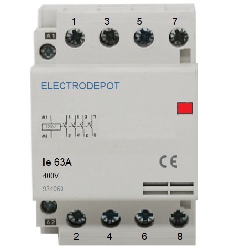
Typical load transfer switch diagram (contactor type) 3 and 4 poles. In an industrial setting a plc is not simply plugged into a wall socket. 1no1nc is generally used to describe contactors (industrial power relays) and manual switches like emergency stop buttons. Contactor or often also called the relay contactor we can find on the electric control panel.
I want star delta power and control wiring diagram with full detail if you give me this please full drawing means from starting to end point like as no/nc of timer and connector please give. The contactor is an electrical component that serves to connect or disconnect ac power. In electrical panels, the contactor is often used as a selector or transfer switch and interlock on the ats system. A wiring diagram is limited in its ability to completely convey the controller's sequence of operation.
Caterpillar 246c shematics electrical wiring diagram [pdf, eng, 927 kb]. Many large pieces of equipment are powered directly from high voltage contactors are used to provide this isolation. If there are wires on all 3 no nc com terminals, you have to reprogram timer. The contactor is powered by another device that is not able to handle the current.
Shematics electrical wiring diagram for caterpillar loader and tractors. Related searches for contactor wiring no nc meaning wiring a contactor diagrammagnetic contactor wiringsquare d contactor wiring diagramlighting contactor wiring diagram2 pole contactor wiring diagram3 phase contactor wiring diagramcontactor wiring diagram ac unitreversing contactor. About 5% of these are contactors. You need a wiring diagram for the unit and have to use a meter to check voltages for the contactor.
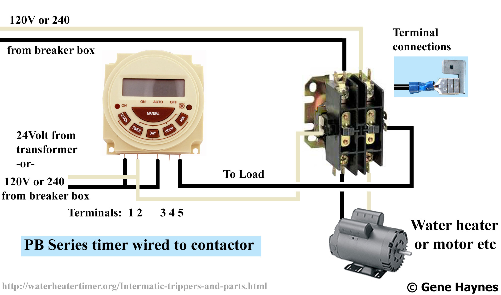
Class 5 13 21 31 43 a1 no nc nc no e1 a1 no nc nc no a2 14 22 36 48 e2 a2 14 22 32 44 2 n.o. Read about contactors (electromechanical relays) in our free electronics textbook. Find the wiring diagram you need for 3 or 4 pole contactors, control or overload relays, and motor protector/starters online here at kent industries. How to wire a contactor.
The drawing for vfd start stop wiring diagram from panel.vfds are called as variable frequency drive or variable voltage variable frequency drive. 32 to 56a • dc control coil • dc control coil with low consumption. Ppt, pdf, txt or read online from scribd. Nc is the abreviation for a normally closed contact of a relay or contactor no is the abreviation for a no stands for normally open, and nc stands for normally closed.
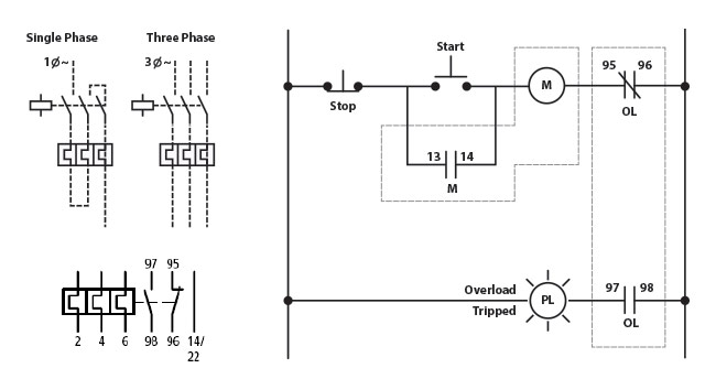
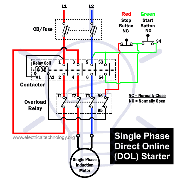
3 pole contactor with 1 n.o. Mc motor starter wiring diagram with cb,mc,o/l, no, nc. The symbol diagram is best but every one can't understand it easily that why i always the above is example diagram of contactor wiring with overload relay, and i hope that this diagram help newbie very mush. The terminals of these coils are arranged on the contactor with simple wiring.
Furthermore, the distance between the center of the rail and the coil terminals is unified at. Two wire control is normally used for _ or _ installations where an immediate return to service after a power failure is required. R contactors engineered to perform in heavy duty applications. When you press the on push k1 contactor will hold and k1 no1 become nc.
General information a block diagram of a typical installation is shown in figure 2. R contactor us catalog | 1sxu106047c0201. With over 100 years of experience in control, abb meets ac and dc requirements from 63 a up to 5000 a with r contactor range.


