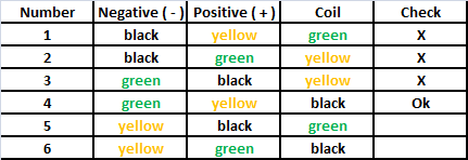
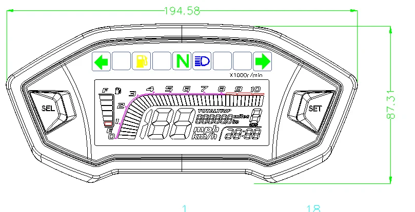
Motorcycle Digital Tachometer Wiring Diagram
Can you guys help me with what resistor i would use for a 2 cylinder tach.
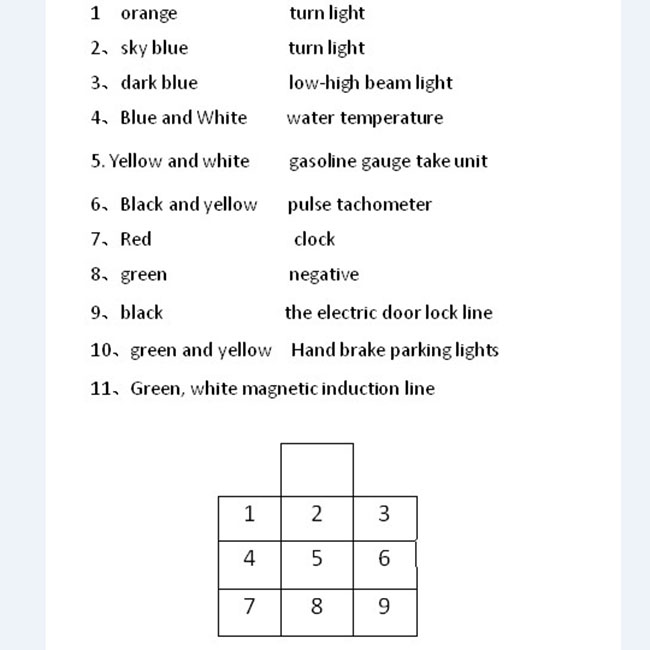
Motorcycle digital tachometer wiring diagram. And what i need for a digital or led readout. Instead of a slotted sensor , it has a reflection based sensor. The tachometers in the diagram use a specific auto meter wiring color code, so if you've got a different. Typically, this feed wire is red.
A tachometer is essential for suitable outboard performance. Get free help, tips & support from top experts on tach adding aftermarket tach, but need wiring diagram for the three vacant plugs under console. Tachometer installation and operation instructions. Digital tachometer, digital tachometer applications, digital tachometer dimensions.
The pulses created by the reed contacts are counted within a certain time interval. Wiring configuration is different than most tachometers. Digital tachometer using arduino plus speed control. Wiring diagram is a technique for describing configuration of electrical equipment installation, for example installation of electrical equipment in substation in cb, from panels to cb boxes which include aspects of telecontrol.
- 1953 Ford Golden Jubilee Wiring Diagram
- How To Wire A Lawn Mower Ignition Switch
- 2004 Jeep Grand Cherokee Front Suspension Diagram
The water temp sensor plug. Totw barons motorcycle tachometer tips and tricks video tutorial. Power leaves the battery from one terminal, passes. 1520 x 2027 jpeg 959 кб.
I am trying to wire up an aftermarket tach and i cannot find a useful connection for the tach signal wire. Prior to installation of your tachometer, check with the ignition box manufacturer for recommended tachometer signal location. Remove the key from the ignition and disconnect the negative terminal from the battery post. Do not deviate from assembly or wiring instructions.
The circuit in the block diagram in figure 1 provide as updated speed data. Get to know the performance of your bike better by installing a digital tachometer to your dash. 2271 x 2470 jpeg 304 кб. Here we are going to design an arduino there are two types of tachometer one mechanical and other one is digital.
The engine speed can be monitored for most efficient operation. Related searches for motorcycle digital speedometer wiring dia motorcycle wiring diagramsmotorcycle wiring diagrams for freeyamaha motorcycle wiring diagramsfree honda motorcycle wiring diagramshonda motorcycle wiring diagrams pdfmotorcycle wiring. The tachometer works according to this principle; Keep checking back for links on how to's, wiring diagrams, and other great information.
This diy digital tachometer for bikes uses two reed switches to get the speed information of the bicycle. That's where the motorcycle wiring harness comes in. Digital led tachometer rpm speed meter with hall proximity switch sensor npn. Motorcycle inner wire motorcycle tachometer wiring harness motorcycle tachometer for ··· docooler digital engine tach tachometer hour meter gauge resettable inductive for racing motorcycle tachometer wiring products are most popular in united states, france, and germany.
This is the circuit diagram of digital tachometer / digital rpm meter which can be used for cars or motorcycles with 2 and 4 stroke petrol engines with any number of. This instructable will show you how to make a portable digital optical tachometer using an arduino uno. This digital diy tachometer for bikes uses two reed switches to get the speed information of the bicycle. Hi i have wired my tachometer as per your diagram and the screen lights up with 4 zeros and the light on the sensor is on but the sensor will not pick up the signal have tried three different magnets and no go what have i.
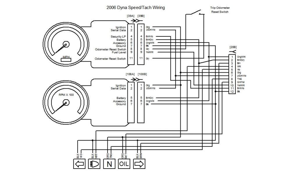
Wire the tachometer to the vehicle as shown in diagram h on the tachometer shuttles back to the tach operating mode, and the digital display now indicates the new shift point. Tachometer installation can be as simple as connecting the tach's sending wire to the negative side of the ignition coil, while other ignition systems feature a dedicated tach sending circuit. Find solutions to your tach wiring diagram question. Speedway motors covers the entire process with our installation of the acewell 1100 digital each wire on the diagram is labeled with the corresponding color.
There are many different ways to wire your motogadget also offers options for electronic flashers, digital gauges, and my personal favorite it's best to think of motorcycle wiring like a circle: Tachometer is a rpm counter which counts the no. Digital bike tachometer ♥♥ this is diagram about digital bike tachometer you can learn online!! Simple but accurate digital tachometer using 8051 microcontroller 8051.
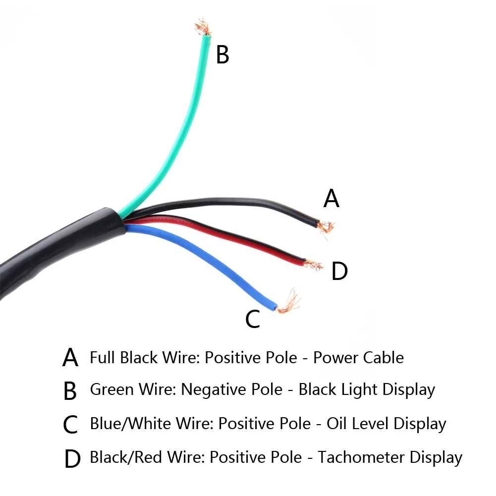
Here we are going to design an arduino based 9 volt battery. Black wire:groundwire,connect with negtive output of battery red wire:power supply,connect to electric door lock outlet wire blue wire:speed signal,connect to ignitor outlet or trigger lines. Read these instructions thoroughly before installing the tachometer. The key switch has two positions.
I have been looking at the circuts diagrams using the lm2917. Learn how to install and wire a digital tachometer. Color motorcycle wiring diagrams for classic bikes, cruisers,japanese, europian and domestic.electrical ternminals, connectors and supplies. Instruction sheet # 0 515 012 037 rev.
The circuit diagram of the digital tachometer using arduino is shown below. If you have any questions, please feel free to email. For programmable tachometer with hourmeter. The reed switches are installed near the rim of the wheel where permanent magnets pass by.
The rpm and all the other informations are displayed on a 162 lcd screen. Tachometers with two or three buttons use an advanced microcontroller circuit to measure engine rpm for increased accuracy and zero pointer flutter at low rpm. A three digit contact less digital tachometer using 8051 microcontroller which can be used for measuring the revolutions/second of a rotating wheel, disc, shaft or anything like that is introduced in this project.

