Mercruiser Trim Limit Switch Wiring Diagram
Auto trim ii system wiring diagram.
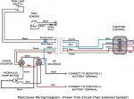
Mercruiser trim limit switch wiring diagram. Hundred of drawings, exploded views, photos and tables. Disconnect the trim limit switch and connect the 2 wires with the blue and purple sleeve together if the trim i have a 2013 4.3l mercruiser and am having a trim switch problem. 3, refer to the mercathode controller wiring diagram. The lanyard stop switch bullet terminals accommodate both mercury outboard and mercruiser applications.
N accessory fuse panel may be connected at this location. Click on links for model pages with spec sheets, manuals, etc. If remote starter switch is not available, disconnect purple wire from ignition coil before using key switch to crank the engine over. Disconnect trim limit switch leads from trim harness.
More than 30+ service & repair manuals for such sterndrive engines as mercruiser you can free download. Because the inefficiency of the propellers at or near the top of the water surface. Use the contact us form at the bottom of the page for any questions. I need help page great for newer boat mechanics.
- Volvo Penta Fuel Pump Assembly Diagram
- Ford F150 Radio Wiring Harness Diagram
- 2006 Ford F150 Fuel Line Diagram
Mercury mercruiser #33 pcm 555 diagnostic service manual + wiring diagrams [pdf, eng, 10.6 mb].pdf. Continuity should be indicated with drive unit in full in/down position. On digital throttle and shift controls, the trim button (if equipped) also functiones as a trailer. Looking for a wiring diagram for a 3.0lx alpha one.can anyone help please.
The linked images are printable but may print across more than 1 page (in order to be legible). The switches are sold in a trim limit/ trim sender switch kit which includes both switches. The diagram below shows the trim limit switch, but i do not understand what flows through the purple w/white or the blue w/white wires. Gry lead for use with service tachometer.
Mercruiser entire parts catalog list gimbal ring and steering lever » 99122a 2. The wires are included in the kit and they are we recommend replacing the shift cable whenever this type of repair is being done. Buy the products and parts you need. Power to switch box #1, switch box #1 to light, light to switch box #2.
If installing on merruiser inboard, rown/white wire is taped back at engine end, or it may be used for an accessory (limit amperes) note : Disconnect trim limit switch leads from trim harness. 1) before connecting the mercruiser scan tool to the thunderbolt v module be sure the engine's ignition switch is in the off position. The local mcm dealer call mercruiser for me today, and they told him the guardian mode will be in effect.
805129a3 trim limit switch is no longer made however we do have a limited quantity of this part available please check our current stock level and order below. I need the color of the wires for a mercruiser 5.0 alpha one ignition. Connect a continuity meter between leads 16 and 17. 4 wiring diagrams mm.0x d note :
We now have sei sterndrive units. Open trim control out/up circuit. Mercruiser service manuals from wholesale marine feature troubleshooting, diagrams, specifications and more. Related with mercruiser trim gauge wiring.
Identify mercruiser outdrive parts with detailed drawings & photos. Sterndrives are trimmed up (out), however control of the boat may be limited or altered. Simple to follow illustrated procedures. Connect a continuity meter between leads 16 and 17. in quotation marks, e.g.
Trailer and trailer limit position. Troubleshooting, specifications and wiring diagrams. Note:refer to mercathode controller wiring diagram. Mercruiser power trim system wiring diagram at performance product technologies/ishopboating.com.
Wiring diagrams for yamaha golf carts valid wiring diagram for 2002. Fresh tilt and trim switch wiring diagram. Outdrives which only had 1 limit switch which was mounted in the top, center of the gimbal housing, is no longer available from mercruiser. Also because i need to bring power to the key switch somehow so thought i would do it the old fashioned way.
Read more about shift cables at replacing your mercruiser alpha or. Normally closed reverse interlock switch. Step by step instructions detailing how to remove a mercruiser bravo sterndrive to repalce the trim position sender and trim limit switches. Disconnect mercathode wires from mercathode controller if equipped.
The table of contents of the clymer® mercruiser® service manual is as follows This engine had an aluminum block with cast in iron cylinder sleeves and was created by mercruiser and cast like mercury outboard engines. I need help page to identify components with detailed drawings and photos. This diagram is a thumbnail.
2002 buick century fuel pump wiring diagram , 1998 chevy cavalier stereo wiring diagram , new holland ls180 starter wiring diagram , welding set diagram , 1995 ford mustang fuse box location , free hvac wiring diagrams , x18 pocket bike wiring. Faulty trim limit switch or leads.


