Leeson Single Phase Motor Wiring Diagram
Electric motor wire marking & connections.
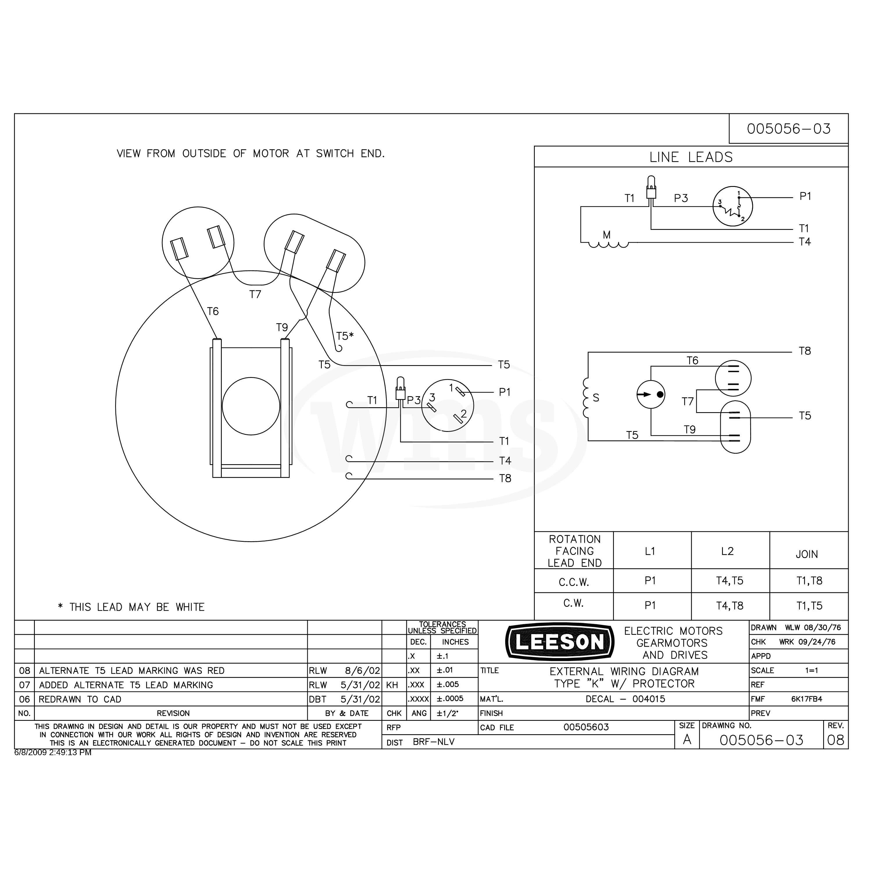
Leeson single phase motor wiring diagram. The previous owner was not using this capacitor. The post discusses a single phase variable frequency drive circuit or a vfd circuit for controlling ac motor sped without affecting their operational specifications. Motors and other similar inductive loads specifically do not like operating with. I am making the assumption that the machine is fed with a single phase 240 volt supply, the motor is single phase 240 volts and the lamps you use are 240 volts.
The complete guide of single phase motor wiring with circuit breaker and contactor diagram. Related searches for single phase 220v motor wiring diagram single phase motor connections diagramswiring diagram for 220 motor120 220 motor wiring diagramwiring diagram. What is the wiring diagram to run it under 230vac? Wiring diagrams for groschopp's ac single and three phase motors.
What happens to a 240v electric motor if you hook up the same phase 110v to each of the 2 lines it.motor. In this video, jamie shows you how to read a wiring diagram and the basics of hooking up an electric air compressor motor. In particular, the vfd must be sized accordingly and a 3 phase motor vfds and single phase ac motors. This is what i purchased.
That is not a single phase motor, that is a three phase motor. Skip to main search results. 2 hp single phase 220 volt. Get free help, tips & support from top experts on leeson motor wiring related issues.
Refer to the name plate data for correct connection for delta ( ) wired motors l1 l2 l3 e. Single phase fully controlled rectifier. I am starting pretty much from scratch. Post a photo of the name plate and any diagram you may have.
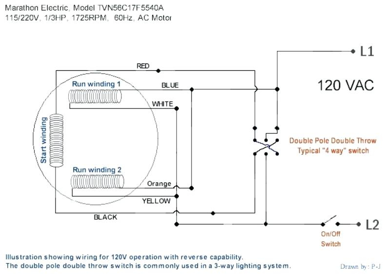
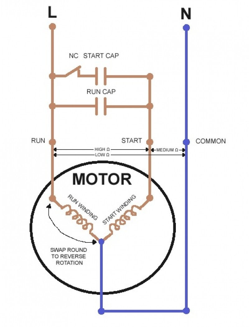
Single phase motor wiring diagram with capacitor sources. Wiring diagrams, sometimes called main or construction diagrams, show the actual connection points for the wires to the components and terminals of the controller. Home>electrical wiring installation>single phase & three phase wiring diagrams note: How do i connect the wires into the motor with cap run cap start for forward and reverse.
The wiring diagram is typically on the reverse of the cover plate. I also published 3 phase motor wiring diagram which wired with contactor. The motor is supplied from a single phase fully controlled converter operating from a 230 v. How to install and wiring capacitor for three phase motor with single phase power supply?
Single phase applications require special consideration when applying a vfd. Sometimes there are wiring diagrams in the peckerhead (little junction. 1(a) shows the circuit diagram of a single phase fully controlled halfwave rectifier supplying a purely resistive load. 0.25 kw, 0.33 hp single phase electric motor 240v 1400 rpm.25kw/1/3hp 250 watt | ebay.
How to use the motor search tool. These tips can be used on most. The old starter wiring and blocks are shot.50+ years old. The single phase motor are those motor which is working one phase and neutral (ground) supply for doing his duty and a 3 phase motor required 3 phase power source.
Electronic starter for single phase motor is used for protecting motor from over currents and protection scheme of single phase induction motor. I have a single phase 3 wires ( + ground ) submersible pump , i need to understand the correct wiring what type of motor is this and is the capacitor important ? 3ø wiring diagrams diagram dd1.


