Idec Relay Wiring Diagram

Diagram Database All Diagram Database Website

Sh2b 05

Yy 9996 Idec Rh2bulcac24v Relay Wiring Diagram Schematic Wiring
About 0% of these are wiring harness, 1% are contactors, and 0% are voltage regulators/stabilizers.
Idec relay wiring diagram. Alibaba.com offers 865 relay wiring diagram products. How a circuit is represented in a circuit diagram. The coil of wire causes an electromagnetic field. The polarity of the voltage does not matter.
Relay logic demonstrates different relay wiring configurations to connect relays for different types of switching applications. Connect an arduino's pin to the in pin of the relay. Place the relay's rated coil voltage on these terminals. Electronics tutorial about the relay switch circuit and relay switching circuits used to control a variety of loads in circuit switching applications.
Omron safety relay wiring diagram gallery. Page 5 the wiring information in your idec smartrelay manual is also found in the idec smartrelay product info included with all devices. Optocoupler is a component that transfers electrical signals between two state of isolation circuits by using light, and prevent high voltage from affecting the system receiving the signal. Actual wire colors differ by country and/or voltage.
- 1979 Bronco Fuse Box Diagram
- 1999 Freightliner Fl80 Fuse Box Diagram
- Ge 30 Amp Disconnect Wiring Diagram
Relays are electromechanical devices that use an electromagnet to operate a pair of movable contacts from an open position to a closed. Relays take a relatively small amount of power to operate the relay coil, but the relay itself can be used to control motors, heaters, lamps or ac circuits which themselves can draw a lot more electrical power. It shows how the electrical wires are interconnected and can also show where fixtures and components may be connected to the system. This includes ac schematics and dc schematics and diagrams that prominently feature relaying.
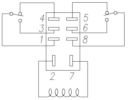
As relay diagrams show, when a relay contact is normally open (no), there is an open contact when the relay is not energized. A motor starter is just another name for a certain type of relay that is used to control a motor. The default position of the relay is when the relay is deactivated, the active position is when pin 8 has 12v on if the relay extends, just flip the connections on 5 and 6. The square relay pinout shows how the relay socket is configured for wiring.
Wiring a denso relay is extremely simple. The 2 coil terminals is where the voltage is placed in order to energize the coil. See the wiring diagram for details. The wiring diagram is given below to help this wiring method is fully compatible with any 4 pin denso relay starting with the serial number 156700 or look like the sample denso relays below.
The wire colors shown in figure 1 in the diagrams color code table are examples only. How to convert a basic wiring diagram to a plc program. To remove idec smartrelay, proceed as follows: Relay wiring diagram lights notes:
Separate wiring diagram symbols • each input line of the eb3c makes up one independent intrinsically safe circuit. Here we look at relay switch pin diagram and the different kinds of relay switches. 3052 x 1931 jpeg 450 кб. You just need to buy a separate relay harness to install it properly.
Idec rh2b ul wiring diagram | free wiring diagram. Reading guidelines for ac and dc schematics in protection and control relaying (on photo: We stock a large range of relays. Earth brown to ground relay white supply led fuse 3a yellow green load black switch right high beam to fuse ground 20/25a hi beam low beam +12v battery +12 vdc battery kc hilites, inc.
Contact multiplier relay wiring diagram. The relay system bypasses the stock headlight wiring, which isn't heavy duty enough to handle the increased wattage. Insert prerequisites for relay outputs you can connect different loads to the outputs such as lamps 3.3 from the circuit diagram to idec smartrelay. The following diagram shows how to.
Here k2 contactor is a contact multiplier relay. Understanding relays & wiring diagrams what is a relay and how does it work? A wiring diagram is a simple visual representation of the physical connections and physical layout of an electrical system or circuit. 492 x 363 jpeg 51 кб.
1.din rail interface relay modules 1/2/4/6/8/10/12/14/16 channels optional; Control the relay by programming the pin to low or high. Installing and wiring idec smartrelay removing. In the above wiring diagram we have kept the jumper in place, due to which the electromagnet of the relay will be driven directly from the arduino.
Additional support at our internet address you can quickly. A relay is an electrically operated switch that can be turned on or off, letting the current go through or not, and can be controlled with low voltages, like the 5v provided by the arduino pins. Contact multiplier relays are connected in parallel with the breaker contact. This is the diagram below to learn all the pin terminals of a double pole double throw (dpdt) relay:
This page demonstrates several simple ways to wire a relay for various applications. I keep getting asked the same thing over and over so here's a reply i did to a post long ago. The armature opens and closes the contacts. Electromechanical relays may be connected together to perform logic and control functions, acting as logic elements much like digital gates unlike schematic diagrams where the association between relay coils and relay contacts is represented by dashed lines, ladder diagrams.
Trailer wiring diagram electrical circuit diagram electrical wiring diagram light switch wiring boat wiring car horn car audio installation wire/fuse size & relay explanations. It just connected in series with the closing coil's potential free contact. Switching current upto 8a at 250vac or 30vdc; A wide variety of relay wiring diagram options are available to you, such as application, type.
In the below diagram i completely wire a 3 phase motor because if i did not shown the complete method and only shown the phase controller then you in the above diagram i shown the complete method of wiring or connection of phase failure relay diagram with circuit breaker, cont actor. Relay schematics and diagrams the example relay diagrams below show how a relay works. Controlling a relay module with the arduino is as simple as controlling any other output as we'll see later on.
Gallery of Idec Relay Wiring Diagram
How To Wire A Relay

Diagram In Pictures Database Idec Relay Wiring Diagram

Wrg 9165 Idec Relay Socket Wiring Diagram
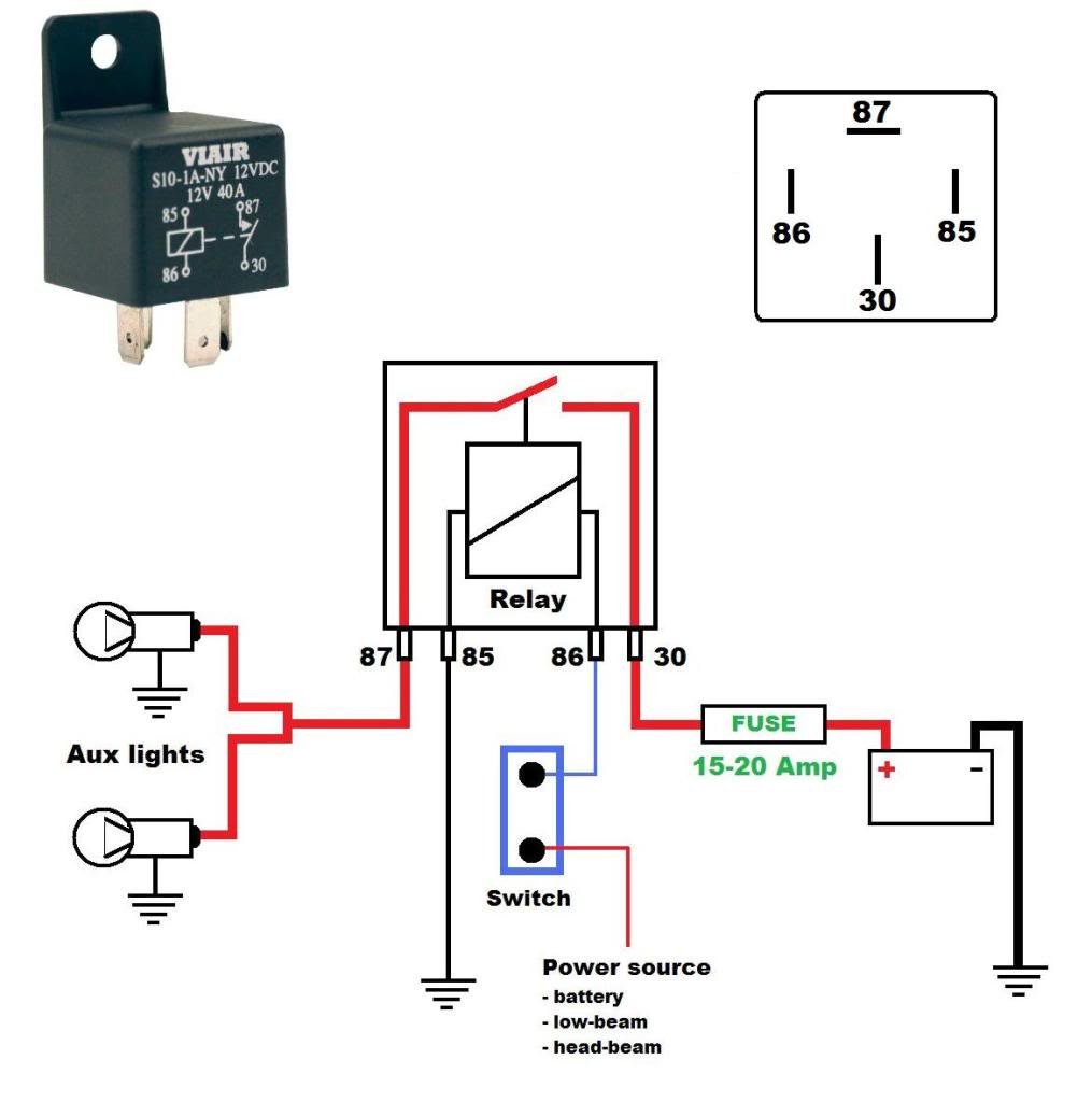
Diagram Idec Relay Wiring Diagrams Full Version Hd Quality

Idec Dpdt Relay Wiring Diagram Auto Electrical Wiring Diagram

Diagram Idec Ice Cube Relay Diagram Full Version Hd Quality

Diagram Jeep Cj5 Horn Relay Wiring Diagram Full Version Hd

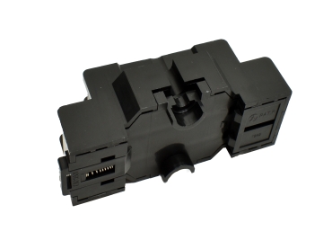
Idec Sr2p 06 Relay Socket Din Rail Screw 8 Pins 10 A 300 V Gt3 Series

Om 3672 Idec Relay Wiring Diagram Get Free Image About

Diagram Idec Relay Wiring Diagram Picture Schematic Full

28 Idec Sh2b 05 Wiring Diagram Wiring Diagram Full Version Hd

Diagram Idec Ry4s Relay Wiring Diagram Full Version Hd
Sh2b 05 Idec

Diagram Idec Relay Wiring Diagram Schematic Full Version Hd
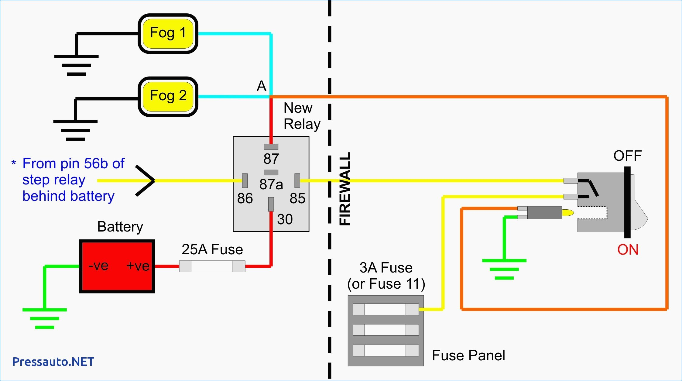
Diagram Idec Ice Cube Relay Diagram Full Version Hd Quality

Diagram Idec Relay Wiring Diagram Full Version Hd Quality

1997 Jeep Grand Cherokee Laredo Wiring Diagram In 2020
