Goodman Air Handler Wiring Diagram
The wiring diagram for the air handler is generic of course, so i assume that might explain some of the inconsistency.
Goodman air handler wiring diagram. Goodman air handler wiring diagram dolgular furnace. Goodman furnace wiring diagram aepf thermostat control easy. May 16, 2019may 15, 2019. This video is to be used as a reference for the low voltage control wiring of your heating and ac system.
.goodman thermostat manual goodman manuals air conditioners goodman air handler manual goodman owners manual goodman ck36 1b manual goodman parts manual goodman amana central air conditioning wiring diagrams most of the time. Always refer to your thermostat or equipment for. Copyright © 2020 goodman manufacturing company, l.p. Variety of goodman aruf air handler wiring diagram.
For split system air conditioner goodman split system wiring diagram air. Wiring diagrams are often on the blower housing, or elecrical compartment. W1 and w2 are your back up elec. Manual de instrucciones goodman mfg.
- 2001 Polaris Scrambler 90 Wiring Diagram
- 98 Ford Windstar Fuse Diagram
- Honda Shadow 750 Carburetor Diagram
Goodman air handler wiring diagram. Goodman global and goodman manufacturing, founded in 1982, is currently (2017) a member of the daikin group, osaka, japan, after being purchased in 2012. Instructions for the furnace or. Goodman air handler wiring diagram.
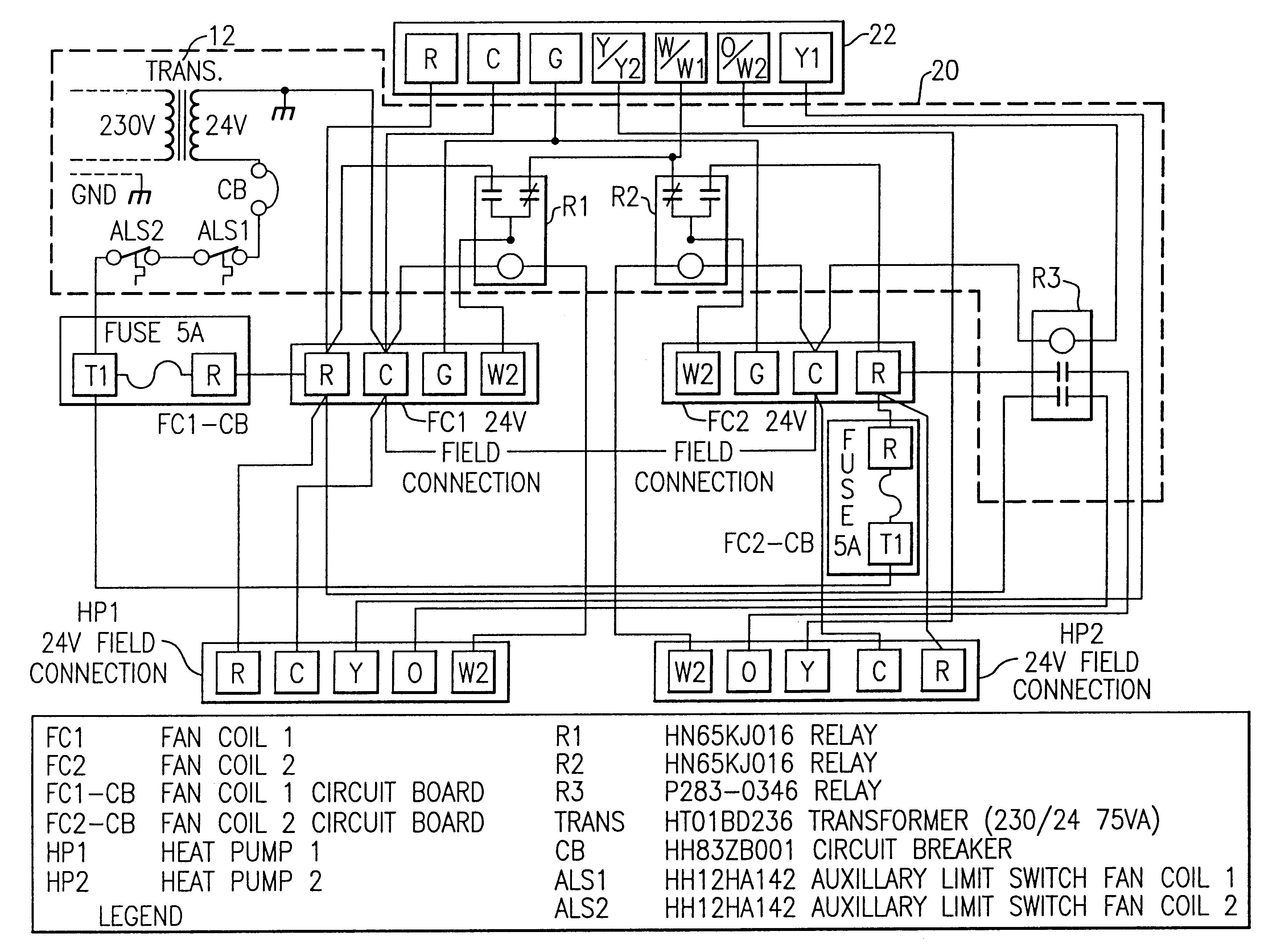
Wiring diagam for goodman heatpump. Goodman air handlers are known for their competitive price and the excellent warranties from goodman manufacturing, now part of daikin. Models compatible with goodman's comfortnet communicating system are available in addition to standard air handers. Related content for goodman avptc 24b14a series.
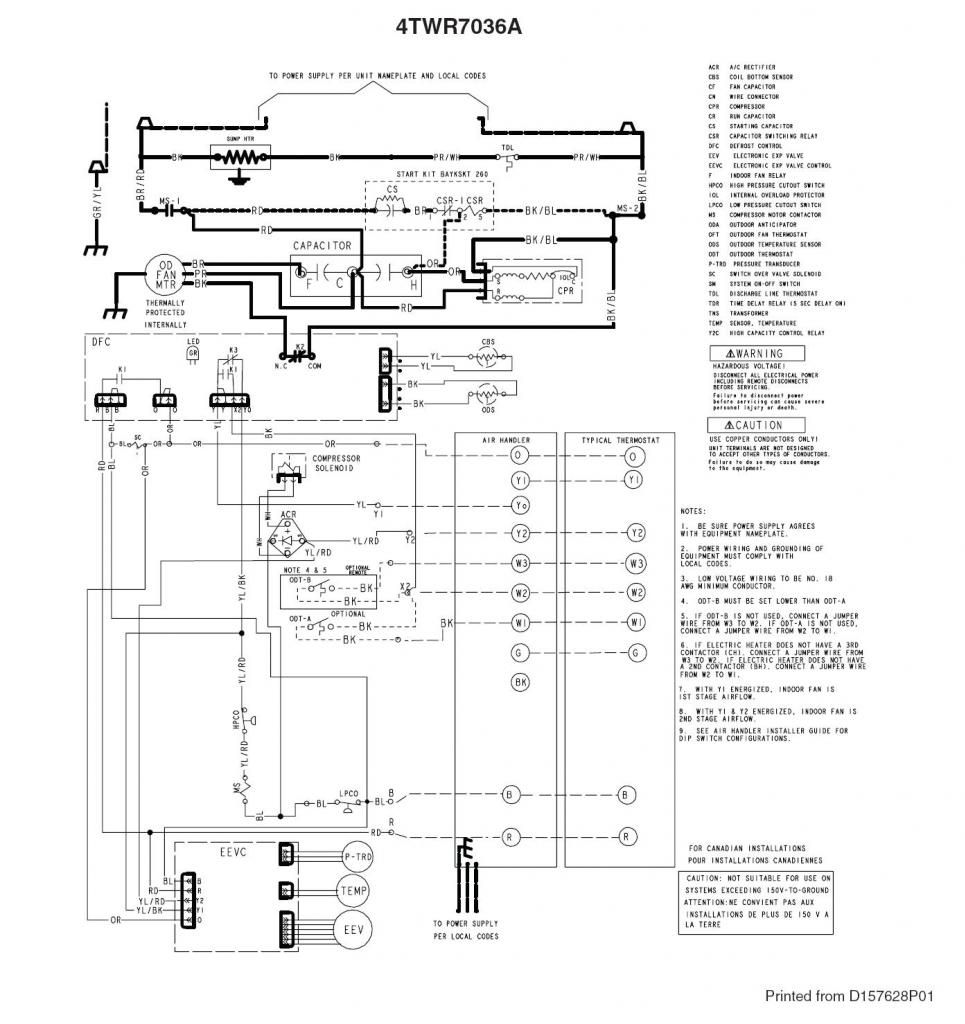
Goodman aruf wiring diagram golkit. Download manuals & user guides for 68 devices offered by goodman in air handlers devices category. Electrical wiring diagrams for air conditioning systems †part two. A wiring diagram usually offers details regarding the family member setting and also setup of devices as well as terminals on the gadgets, to assist in file type:
■ if the air handler is installed in an unconditioned space, sealant should be applied around the electrical wires see wiring diagram—electric heat and blower in the make electrical connections section. Once received, the air handler will send the low stage cooling airflow demand to the ecm motor. It shows the elements of the circuit as streamlined shapes, and also the power and also signal connections in between the devices. You didn't say whether you are looking for the unit diagram or heat kit diagram goodman is also very good about putting a wiring diagram somewhere on the inside access panels of all their units so be sure and look there first.
Once goodman/amana sent the manual that had the wiring diagram for a 2 stage cooling setup, it became clear. Goodman air handler wiring diagram. A wiring diagram is a streamlined traditional pictorial representation of an electrical circuit. Y is your cooling circuit and will be the same in the air handler and heat pump unit, use the yellow wire for this circuit.
We also have installation guides, diagrams and the diagram(s) below can help you find the right part. Duplication in part or in whole is strictly prohibited. Air handlers installation & operating instructions. If you'd like help, we invite you to call our customer service number at the top of the page, or click chat.
Choose one of the enlisted appliances to see all available service manuals. Heat pump air handler changing blower speeds. Aruf**14 series electrical and control wiring.


