Draw The Shear And Moment Diagrams For The Compound Beam
Answered Draw The Shear And Moment Diagrams For Bartleby
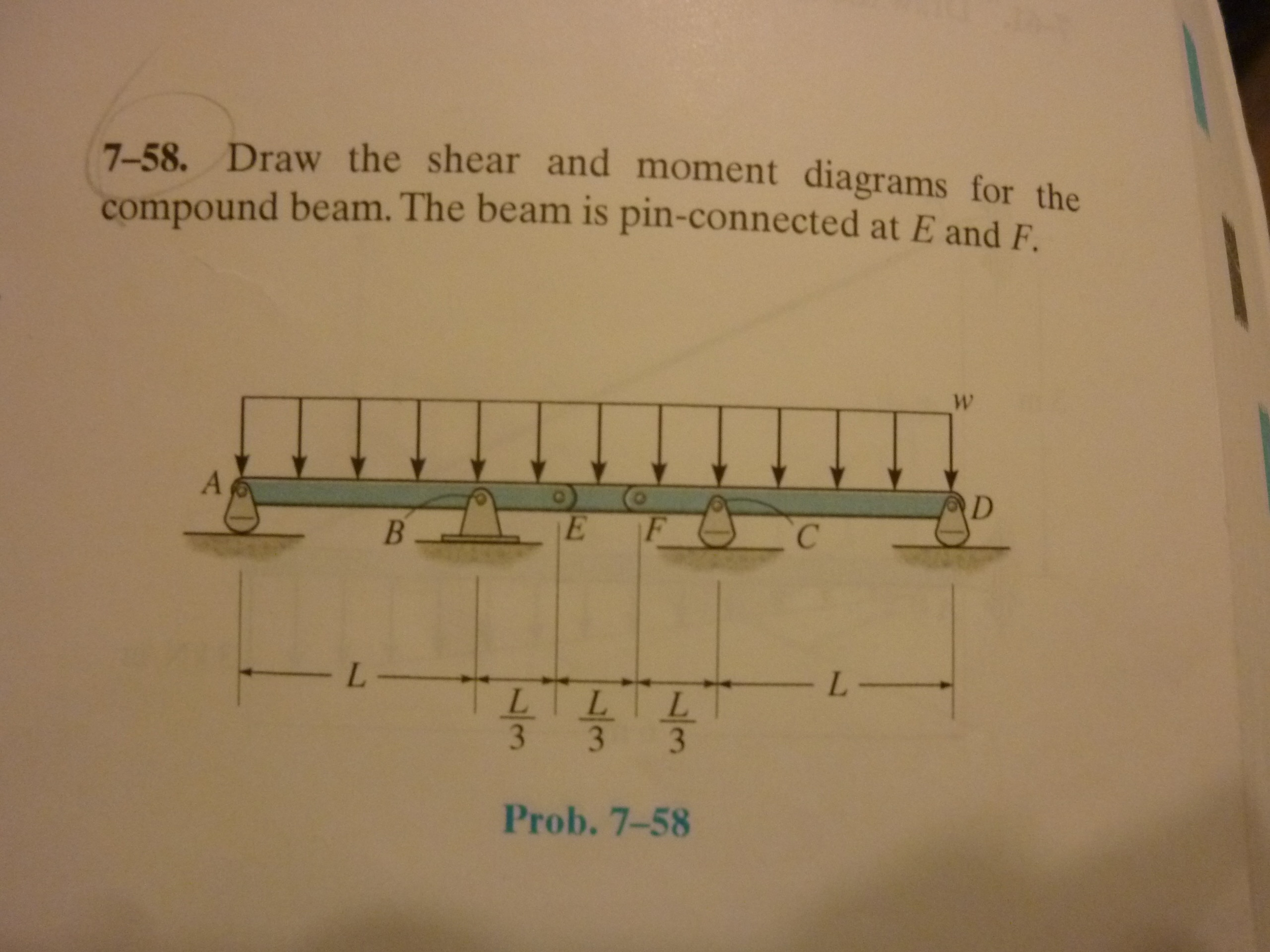
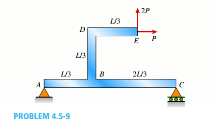
Draw The Shear And Moment Diagrams For The Compound Beam Shown
0133254445 Ism06 184704 Mechanics Of Materials Cve 224
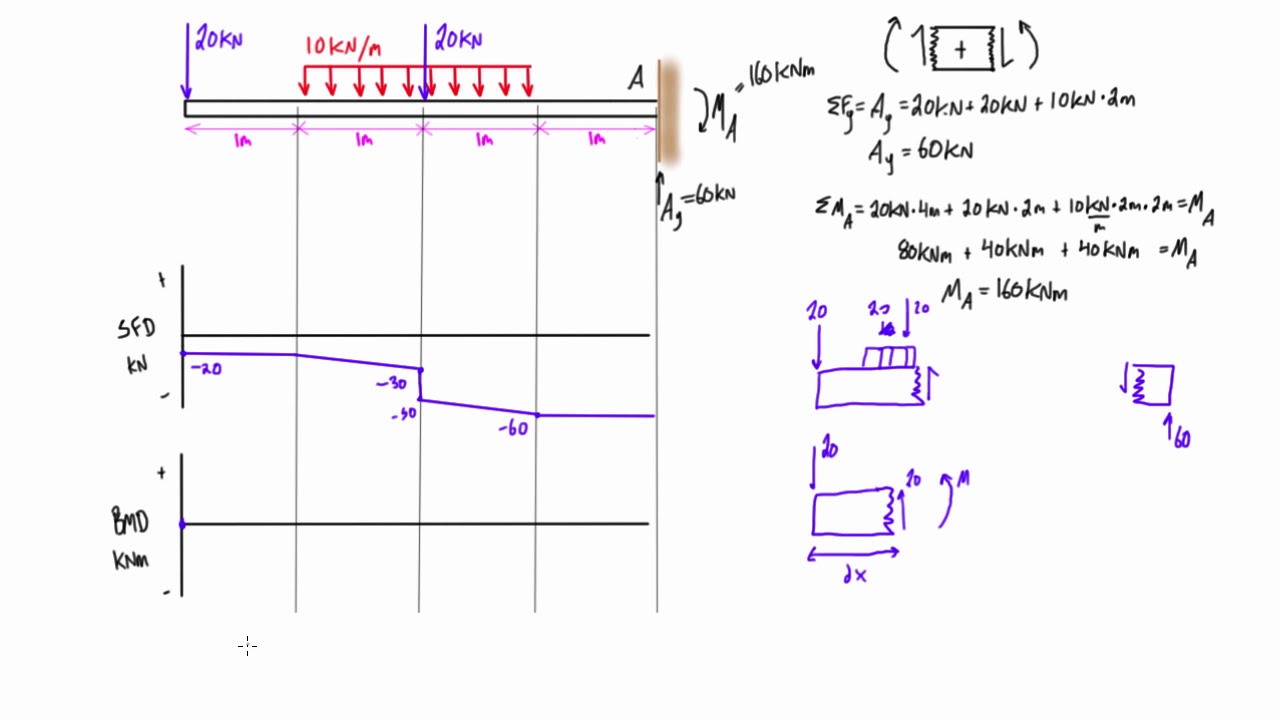
Since the total weight is located in the middle of beam, the support.
Draw the shear and moment diagrams for the compound beam. Homework statement draw the shear diagram for the compound supported beam. Resistance to bending and shear force is given more importance than resistance to normal force in most cases involving beams. Ø consider the beam shown below subjected to an arbitrary loading. For more details check these videos.
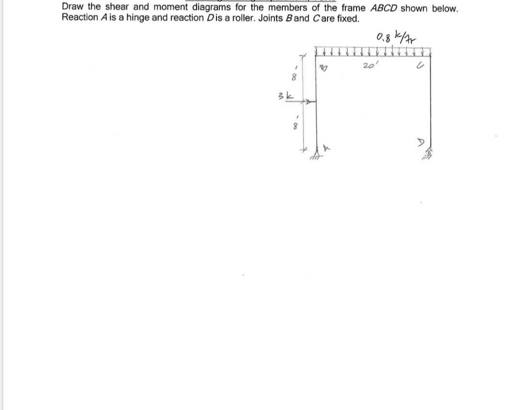
Shear force and bending moment values are calculated at supports and at points where load varies. Civil engineering q&a library draw the shear and moment diagrams for the members of the frame abcd shown below. Displayà show load assign à frame/cable/tendon on the pop up window click make sure that show joint loads with span loads and show span loading values are. In general the process goes like this:
This material is protected under all. Beam, draw, connected, diagrams, compound. 1) under the shear diagram, drop vertical lines at every point of interest including every time the shear diagram clockwise external moments applied to a beam cause the internal moment in the beam, to the right of the application point, to go positive (or more. Calculate the deflection of steel, wood and other materials.
- Craftsman Gt5000 Belt Diagram
- 2001 Chevy Silverado Tail Light Wiring Diagram
- 2010 Dodge Caliber Belt Diagram
A shearing force occurs when a perpendicular force is applied. Proceeding from one end of the member calculate and draw the shear force and bending moment equations for the given structure. A c b 4 ft 6 ft 4 ft 4 ft 331 06 solutions 46060_part1 5/27/10 3:51 pm page 332 © 2010 pearson education, inc., upper saddle river, nj. The beam is loaded and supported as shown in the figure.
Shear and bending moment diagrams are analytical tools used in conjunction with structural analysis to help perform structural design by determining the value of shear force and bending moment at a given point of a structural element such as a beam. Drawing shear force and bending moment diagram for a compound beam. So sum of moments at any point i summed the forces in the y direction, as well as the moments at a and moments at b, but using these 3 equations causes the variables to cancel. This expansive textbook survival guide covers 11 chapters, and 1135 solutions.
Write shear and moment equations for the beams in the following problems. The shape of bending moment diagram is parabolic in shape from b to d, d to c, and, also c to a. Drawing shear force and bending moment > how to find a shear force diagram (sfd) of a simple beam in this tutorial, we will look at calculating the shear force diagram of a simple beam. Draw the shear and moment diagrams for the compoundbeam.
A cantilever beam carries a uniform distributed load of 60 kn/m as shown in figure. Write equations for the shear v and bending moment m for any section of the beam in the interval ab. For the distributed load to show select: 44 shear and oment diagrams eample draw complete shear and bending moment diagrams for the beam.
Draw the shear and moment diagrams for the beam? Simply supported beam with point load example. Sher nd oent digrs (grphicl) (5.3) slide no. Write equations for the shear and bending moment for any section of the beam in the interval b.
Shear force and bending moment diagram of simply supported beam can be drawn by first calculating value of shear force and bending moment. For the first part on drawing the moment diagram, instead of a curve line it suppose to be a straight line. This textbook survival guide was created for the textbook: Bending moment diagram (bmd) shear force diagram (sfd) axial force diagram.
Use this beam span calculator to determine the reactions at the supports, draw the shear and moment diagram for the beam and calculate the deflection of a steel or wood beam. The beam and loading shown. Students also viewed these civil engineering questions. Reaction a is a hinge and reaction dis a roller.
Figures 1 through 32 provide a series of shear and moment diagrams with accompanying formulas for design of beams under various static loading conditions. Draw the shear force diagram and bending moment diagram for the beam. Draw the shear and moment diagrams for the compound beam. In each problem, let x be the distance measured from left end of the beam.
When drawing a bending moment diagram, under a udl, you must connect the points with a. Just like a pivot rule: To complete a shear force and bending moment diagram neatly you will need the following materials. Sketching the deflected shape of a beam or frame.
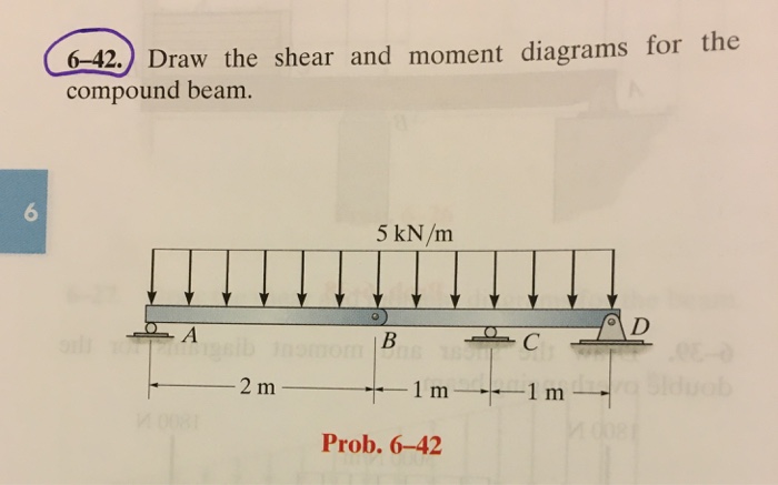
To construct a moment diagram. Draw the shear and moment diagrams for the 6 kip 8 kip compound beam which is pin connected at b. This is an example problem that will show you how to graphically draw a shear and moment diagram for a beam. Beam formulas with shear and moment.
This full solution covers the following key subjects: Draw the shear and bending moment diagram for. Shear and bending moment diagrams depict the variation of these quantities along the length of the member.
Gallery of Draw The Shear And Moment Diagrams For The Compound Beam
Solved Draw The Shear And Moment Diagrams For The Compoun

Solved The Compound Beam Abcde Shown In The Figure
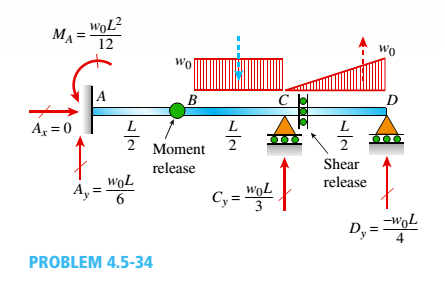
A Compound Beam See Figure Has An Internal Moment Release

Draw Shear And Moment Diagram For Beam Facebook
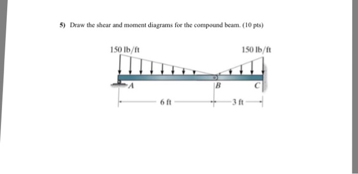
Solved 5 Draw The Shear And Moment Diagrams For The Comp
Solved Draw The Shear And Moment Diagrams For The Compoun

The Compound Beam In The Attachment Is Fixed At A Pin

Draw The Shear And Bending Moment Diagrams For Members Ac And
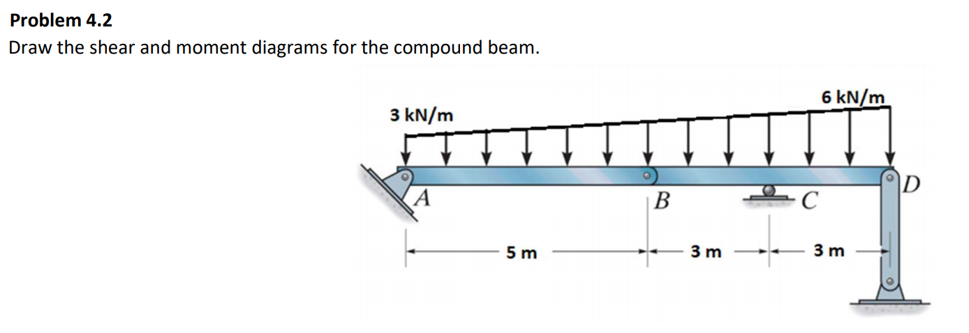
Solved Problem 4 2 Draw The Shear And Moment Diagrams For

Diagram Tree Shear Wiring Diagram Full Version Hd Quality
Chapter 4 Internal Forces In Beams And Frames In
Shear Force And Bending Moment Diagram Practice Problem 5
A Simply Supported Beam Abc Is Loaded At The End Of A Bracket
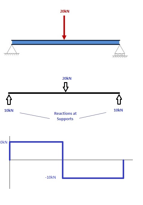
Diagram Electron Beam Diagram Full Version Hd Quality Beam

Engineering Mechanics Statics Pages 351 400 Flip Pdf

Draw The Shear And Moment Diagrams For The Compound Beam Shown

Draw The Shear And Moment Diagrams For The Compound Beam
