Digital Speedometer Wiring Diagram
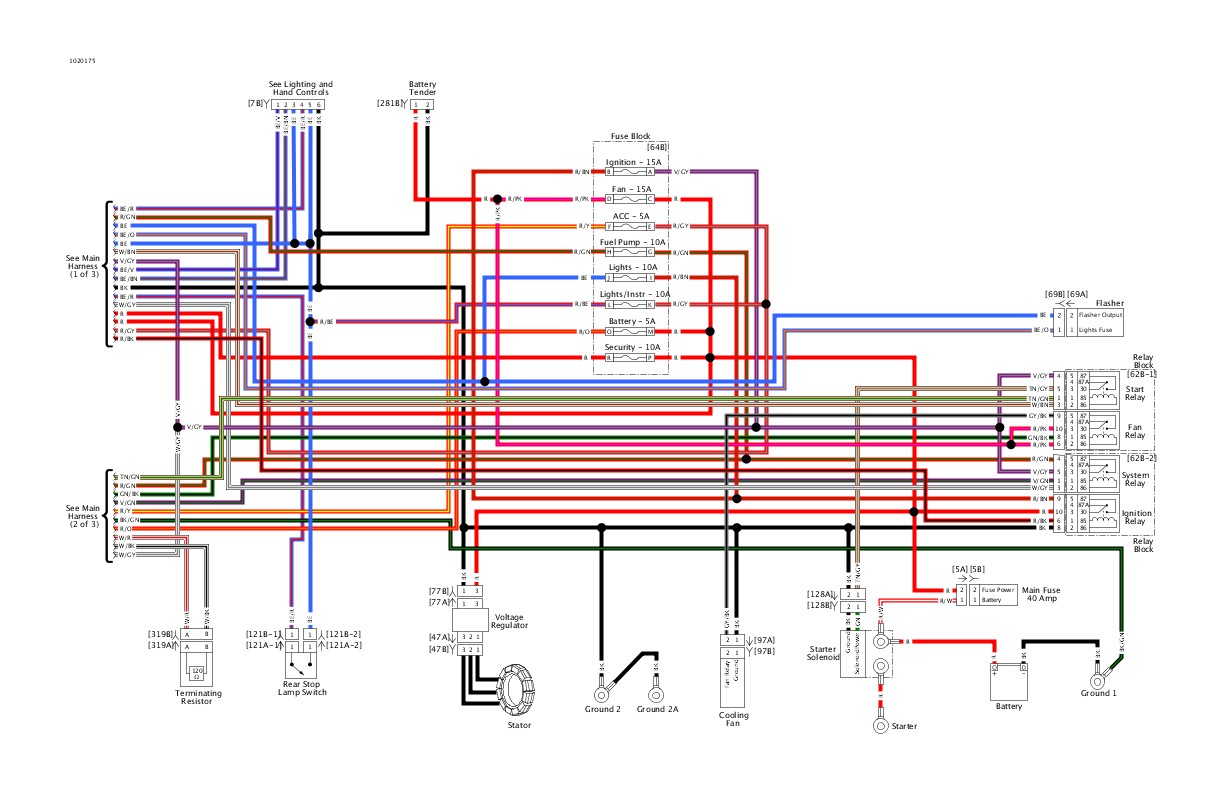
Diagram Dakota Digital Speedometer Wiring Diagram Full
Smiths Digital Chronometric Speedometer Installation Help

Speedometers Smiths Gauges Usa
Configuring the microcontroller development kit.
Digital speedometer wiring diagram. .wiring diagram to connect speedometer with my three wire connector. Here is a diagram, again the highlighted area is where you'll be connecting your wire to. An opaque disc is mounted on the spindle attached to the front wheel of the vehicle. Pin 12 carries the speedometer signal (on the can bus!).
Complete manual and schematic diagram: Digital speedometer with password enable speed controlling a project report abstract the main aim of this project is to design a digital speedometer with passw… fig.2.1 basic block diagram of digital speedometer with password enable speed controlling. The circuit shown below diagrams how to make a digital speedometer which can measure up to 99kmph with a resolution of 1kmph for i.e lml vespa, kinetic honda or some other vehicles using the lm324. I've created a list of improvements that could be made to our project.
Learn how to make a tachometer and speedometer using a c8051 microcontroller, an optoelectronic figure 7. It also may cause a trouble code to be stored, requiring a dealer visit or that fancy scanner someone should let. Universal digital lcd speedometer with rev counter in a plastic case. The speed is sensed by a magnet.
- 2007 Toyota Camry V6 Serpentine Belt Diagram
- 2001 Ford Focus Vacuum Hose Diagram
- 2006 Dodge Ram 3500 Trailer Wiring Diagram
Check the spark plug wires and insure they are emi ram jet engine computers have analog and digital tachometer signals. Speedometer wiring diagramuniversal digital speedometer motorcycle wiring diagram, universal motorcycle lcd digital speedometer wiring diagram, universal. Our tachometers require the digital signal. Pulling it stops the speedometer, and lights up a plethora of warning lights.
The ir led, a phototransistor is mounted. I have all aftermarket gauges in my car and a while ago my aftermarket speedometer died. For wiring of the lights, see diagram d. Need diagram for wiring for 1986 transam.
Wiring diagram ( pin out ) speedometer vario 125/150. Be sure you have the diode orientation as shown in the diagram. Proper wiring of the speedometer with: How to build a digital input and digital control using microchip's rn487x bluetooth module.
Tach filters are not required. Good afternoon, i attached all the diagrams and pinouts i could find. Digital speedometer and odometer based on magnetic hall sensor which is operate by arduino controller. If you have been following the pic tutorials then you can also reuse the hardware that we used for learning pic.
The circuit diagram of this speedometer and odometer project is very simple and can be built on a breadboard. Speedo is with the ability to connect four additional lights (turn signals, high beam, neutral, turns) supports a fuel gauge indicator, gear engaged and recharge status.this item is suitable for f1,2. This digital speedometer displays the speed of the vehicle in kmph. See speedo senders below for available auto meter senders.) the speedometer should be calibrated to ensure accurate operation after installation.
I cut off the ends of the usb cable and stripped each of the wires. This sounds complicated but its really quite easy. Circuit diagram for this analog speedometer is simple, here we have used 16×2 lcd to show speed in digital form and stepper motor to rotate the analog rest of connections are given in circuit diagram. Also the model name cf5135b and down is wiring diagram that could be better.
The digital speedometer works great, but what can you do to it to make it better? Remove the sender switch wire and check the gauge and then ground the wire as well. Reconnect the battery and turn on the ignition to make. This digital speedometer circuit uses ic lm324 which is wired as comparator.
The odometer on this speedometer will read. Digital speedometer narendra wadhwani his instrument displays the speed of the vehicle in kmph. How to calibrate digital speedometer | digital gauge calibration settings. Electrical and technical automotif blog.
Now i will describe how to. Complete code for arduino speedometer is given at the end, here we are. Related searches for motorcycle digital speedometer wiring dia motorcycle wiring diagramsmotorcycle wiring diagrams for freeyamaha motorcycle wiring diagramsfree honda motorcycle wiring diagramshonda motorcycle wiring diagrams pdfmotorcycle wiring. The 2007 model wiring diagram shows pin#3 as the tach output from the speedometer, but that is not shown on later diagrams.
Digital speedometer with an arduino. Digital speedometers are always electronic but analog and be electronic or mechanical. Find solutions to your wiring diagram speedometer question. Also will be nice to connect turning lights, neutral, indicators.
All gauges require 4 things to be connected: You can use 1n4004/3/2 for diodes if they are more available. Two wires for the i2c and two larger gauge wires for power and ground. Digital refers to the display, not the ability to read electronically.
Ic lm324 is wired as a comparator. And sets of the seat belt buzzer every minute forever. Same for the temperature sender. I hope this helps you.
Sure the speedometer is working. Find this pin and more on types of electrical wiring by k. Bad plug wires can cause excessive emi interference and cause the speedometer to be erratic. Ic lm324 is wired as a comparator.
Gallery of Digital Speedometer Wiring Diagram

Fw 1282 Wiring Diagram For Odometer Free Diagram

Koso Rx1 Gauge Chinese Replica From Ebay Stay Away If You

Wiring Diagram Of Motorcycle Http Bookingritzcarlton Info
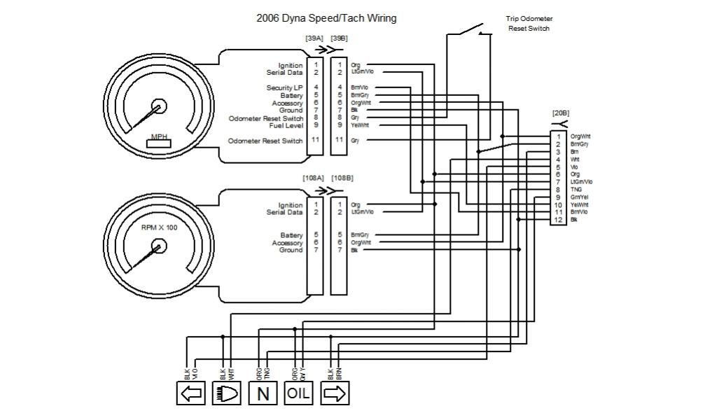
Diagram 2004 Sportster Speedometer Wiring Diagram Full

Zb 5812 Addition Motorcycle Tachometer Wiring Diagram
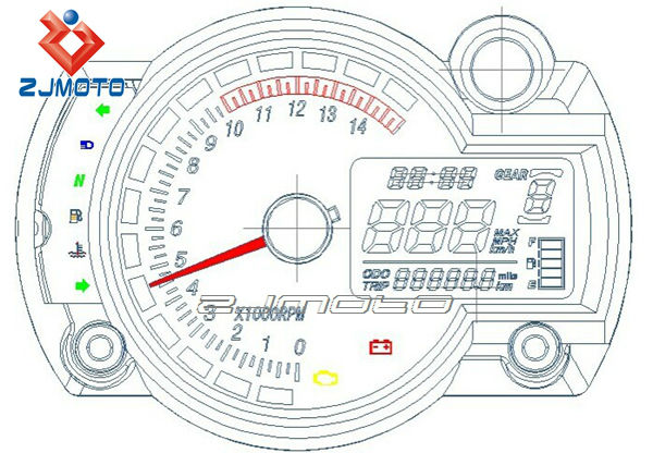
Diagram Wiring Diagram Universal Speedometer Full Version Hd

Diagram Diagram Dakota Digital Speedometer Wiring Diagram
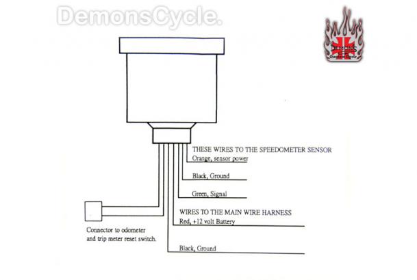
Diagram Vdo Digital Speedometer Wiring Diagram Full Version
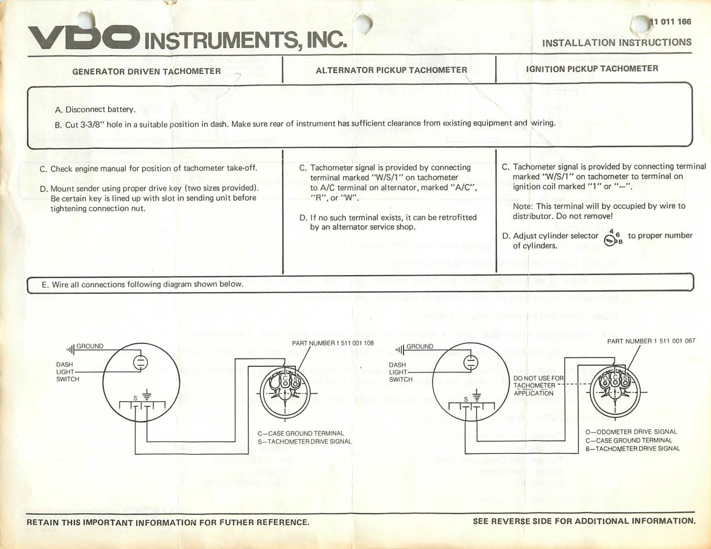
Diagram Diagram Vdo Wiring Gauge Tach Full Version Hd
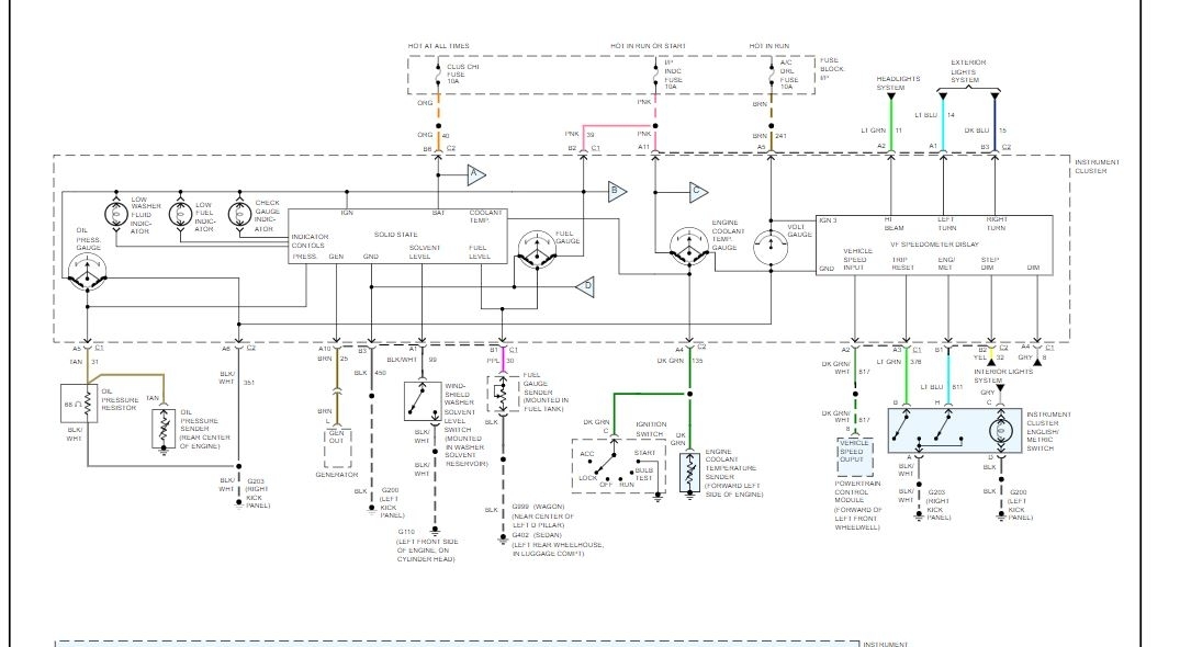
Wiring Diagram Of The Instrument Panel With A Digital

Diagram Dakota Digital Speedo Wiring Diagram Full Version Hd
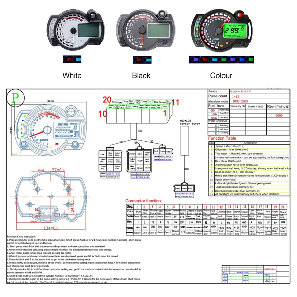
Alconstar 7 Colors Koso Display Motorcycle Digital Speedometer Lcd Gauge Speedometer Tachometer Odometer Instrument Adjustable

Motorcycle Speedometer Wiring Tested

Diagram 94 Sportster Electronic Speedometer Wiring Diagram

Diagram Digital Speedometer Wiring Diagram Full Version Hd

Me 3143 Electric Speedometer With Odometer Wiring Diagram

Reddragonfly 199 Km H 12000 Rpm Lcd Digital Speedometer Tachometer Odometer Mph Kmh For Honda Motorcycle Scooter Golf Carts Atv
