Derive Transfer Function From Block Diagram

Closed Loop Transfer Function Wikipedia
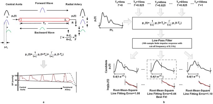
A Simple Adaptive Transfer Function For Deriving The Central
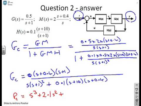
Block Diagrams 8 Tutorial Sheet On Closed Loop Transfer Functions And Use Of Matlab
Example problem on how to derive closed loop transfer function from block diagram.
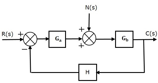
Derive transfer function from block diagram. Consider the block diagram shown below: C1 is an inverse model of the transference function of load disturbance (d). I have this block diagram which i already reduced pretty much: Step 1 − find the transfer function of block diagram by considering one input at a time and make the remaining inputs as zero.
There is one other thing to notice about the system: Block diagrams are a useful and simple method for analyzing a system graphically. When designing or analyzing a system, often it is useful to model the system graphically. To derive the transfer function of a system, we use the following procedures:
The properties of transfer functions derived by reducing block diagrams are the same as those derived directly from differential system equations. How do i derive the transfer function? Exercises are to transform a linear differential equation into the laplace domain transfer functions are compact representations of dynamic systems and the differential equations become algebraic expressions that can be. Lets start by defining wm.
B) simplify the block diagram found in (a) to obtain the transfer function between the power supply of the motor and the speed of my guess, you are trying to use formulas, just derive the equation yourself. A transfer function represents the relationship between the output signal of a control system and the input signal, for all possible input values. The transfer function defines the relation between the output and the input of a dynamic system, written in complex form ( s variable). In this case one could have observed that by moving the summing junction for the.
Derive your closed loop transfer function given a block diagram. When two or more systems are in series. The use of block diagram algebra to nd the system transfer function is advisable for simple systems, but for complex systems it gets quite involved. Derive your closed loop transfer function given a block diagram.
Block diagram algebra is introduced in section 2.3 as a suitable tool for obtaining transfer functions of systems whose block diagrams are known. A block looks on paper exactly what it means: Now i want to derive the transfer function from phi_o1 to q. 1 move middle block n past summer.
Again, this block can be derived from two basic logic blocks. Move node a and close the loop: The transfer function of c2 is c2(s)= kp(1+1/tis) as stated in article. Let us simplify (reduce) this block diagram using the block diagram reduction rules.
Combining the c1 and c2 control signals we obtain the feedfoward. S+2s+3 r(s) → y(s) 2s+3 2 +2s +5 15 automatic control systen. Related threads on get transfer function from block diagram. A pictorial representation of the functions performed by each component and of the flow of signals.
Specifically, the denominator of the transfer function is the characteristic function of the system represented by the block diagram and, when. The block c2 is the pid controller. However i have trouble with the feedback loops since they multiply with each other and i do not know how to reduce that. Lectures aimed at giving an introduction to the definitions and meanings of simple block diagrams and easy to understand methods for computing.
Thus i may find the transfer function of the closed loop. It is not convenient to derive a complete transfer function for a complex control system. Example problem on how to derive closed loop transfer function from block diagram. Develop the differential equation for the system by using the physical laws, e.g a block diagram of a system is a pictorial representation of the functions performed by each component and of the flow of signals.
Now reverse order of summers and close each. Using block diagrams in control systems design. Use the technique of making two different block diagram by dividing two summers and use the approaches of shifting take off point and blocks. ____ transfer functions and block diagrams.
If the transfer function of the system is given by t(s)=g1g2+g2g3/1+x. To prove that the transfer function was correctly calculated, we are going to use a simple xcos block diagram to simulate the step response of the system. It is often not necessary to derive all of the transfer functions directly. It is used to represent all types of systems.
Consider the block diagram shown in the following figure. It can be used, together with transfer functions, to describe the cause and effect relationships throughout the. In engineering, a transfer function (also known as system function or network function) of an electronic or control system component is a mathematical function which theoretically models the device's output for each possible input. But since the sr/rs flip flops are so fundamental in plc programming, they have their own.
Gc represents the controller which produces a signal fs based on superposition principal i can assume that the disturbance signal z0*g12 is zero. I am having trouble to define in matlab the transfer function of the following block diagram. Transfer functions (laplace domain) help analyze dynamic systems. What fbd offers is a way to put functions written with many lines of code into boxes.
Gallery of Derive Transfer Function From Block Diagram
11 10 A Block Diagram Of A Closed Loop System Is Shown In fig

Not Understanding System Dynamics Come Check Out My Full
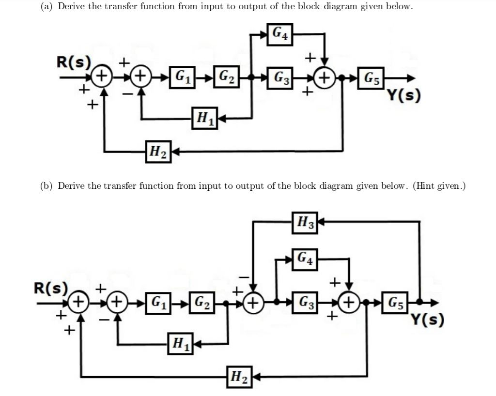
Solved A Derive The Transfer Function From Input To Out
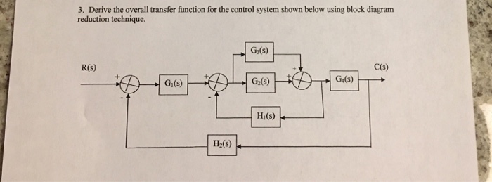
Solved 3 Derive The Overall Transfer Function For The Co

Block Diagram 5

Given The Following Block Diagram With G S 1 S 4s 1
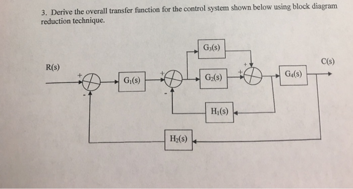
Solved 3 Derive The Overall Transfer Function For The Co
Transfer Function Block Diagram Sytem Dynamics And Control
Control Systems Quick Guide Tutorialspoint
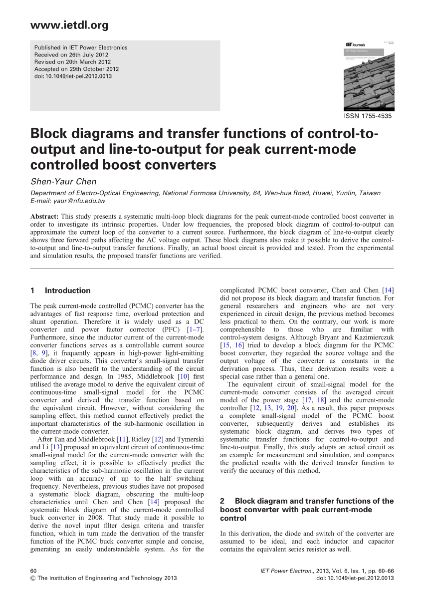
Pdf Block Diagrams And Transfer Functions Of Control
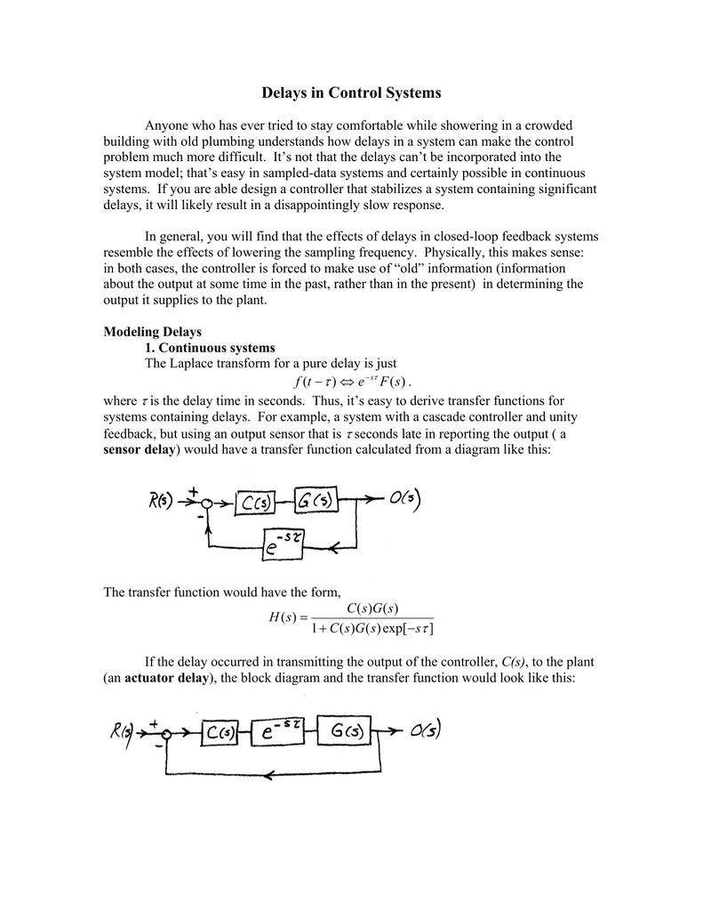
Delays In Control Systems

Draw Schematic Diagram Of Armature Controlled Dc Motor And
Worksheets Automatic Flight Control System Design Ae4301

A I Show That The Sensitivity Of The Closed Loop Transfer
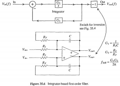
Get Answer 1 Derive The Transfer Function For The Filter
Lecture Notes 27 Dynamics And Control

Solved A Block Diagram For Internal Model Control A
