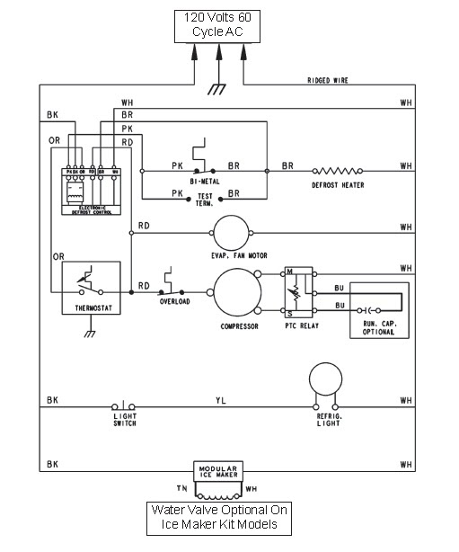
Defrost Timer Diagram
The timer motor in this system, as in the standard feedback circuit, stops during defrost heater operation.
Defrost timer diagram. In older models, the timer runs continuously and roughly every six hours, cuts power to the cooling system and sends power to the. Wiring diagram walk in freezer & defrost timer wiring diagram. Wiring diagram of refrigerator nofrost. In this video you can learn about the defrost timer wiring diagram of a frost free refrigerator and circuit diagram step by step details about the function.
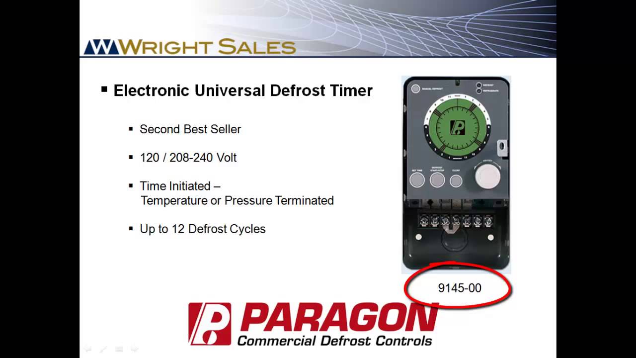
Paragon defrost timer 8145 20 wiring. Orient dc inverter indoor wiring diagram. A wiring diagram is often utilized to repair troubles as well as to earn certain that the connections have actually been made and that every little thing is present. Defrost timer, freezer defrost timer, fridge timer, mechanical timer mechanical timer is widely used in household appliances like toaster, washing machine, electric fan, heater, refrigerator, electric.
This one doesn't show my model number in the list, even though it's on the diagram for il6d. Diagram, paragon defrost timer, refrigeration, refrigerator, timer. There are 2 general types defrost timers. Refrigerator defrost timer wiring diagram wiring diagram new.
You may be a technician who wants to look for recommendations or fix existing issues. Icm 322 defrost timer specifications input •voltage: This category contains defrost timers manufactured by intermatic, mars, supco, johnson controls and paragon which are used to defrost electric or hot gas systems. This circuit is under:, circuits, defrost timer circuits schematic diagram l53630 the job of this timer is to disconnect thecompressor circuit and connect a resistive heatingelement located near.
In this video from sears partsdirect, we'll help you troubleshoot why your refrigerator's automatic defrost system isn't cooling, including checking the electronic control board, defrost heater. All size rotary compressor oil charge ml &capacitor power uf details. A mechanical defrost timer controls the defrost cycle of the freezer. How freezer defrost timer operates charles pen.
With timer in compressor run cycle, check Answer terry, the defrost timer 215846602 is located in the shelves diagram. The cold control, defrost timer, thermostat, defrost heater and the compressor capacitor were all replaced. The defrost timer eventually switches into defrost mode and supplies power to the defrost heater it is usually included in the appliance's wiring diagram which is most often located behind the kickplate.
Defrost timer circuits schematic diagram sample and. Maytag refrigerator wiring diagram inspirational clothes dryer. A wide variety of defrost timer wiring diagram options are available to you, such as applicable industries, showroom location. To check defrost timer 2.
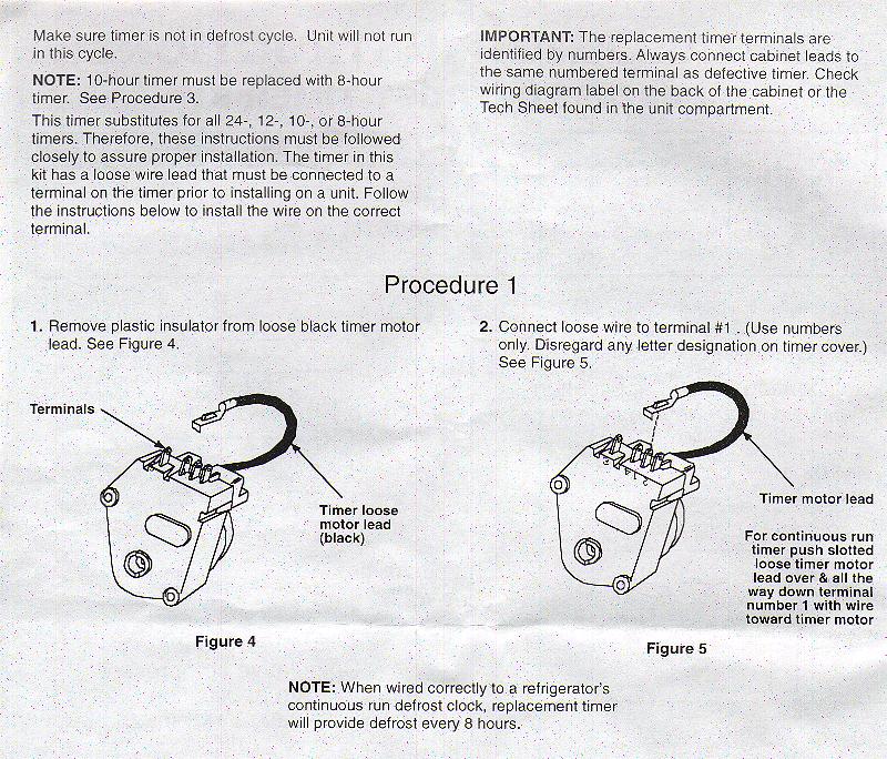
Because this item is not stocked in our warehouse, processing, transit times and stock availability will vary. Refrigerator defrost timer wiring diagram sample. After further troubleshooting i found the existing mechanical defrost timer to be stuck. Modern, state of the art refrigerators use solid state circuitry to control constant or continuous run defrost timers run continuously as long as the refrigerator is plugged in.
Walk in freezer wiring diagram new defrost timer wiring. The contacts are operated by a cam that is gear driven by the clock motor. Wholesaler of a wide range of products which include refrigerator defrost timer, fridge defrost timer, whirlpool defrost timer and samsung defrost timer.


