Defrost Timer Circuit Diagram
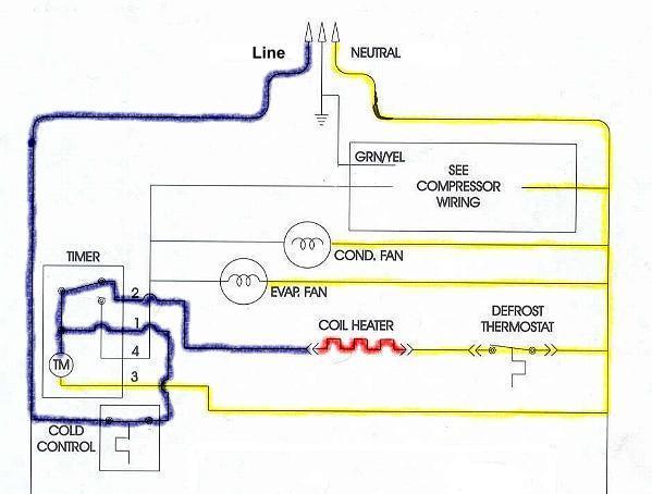
Diagram Refrigerator Defrost Timer Wiring Diagram Full

Refrigerator Defrost Timer Wiring Diagram Diagram

Diagram General Electric Freezer Wiring Diagram Full Version
I had the same issue on my older unit and tore it apart replacing one item at a time over a three month period so answer terry, the defrost timer 215846602 is located in the shelves diagram.
Defrost timer circuit diagram. This circuit is under:, circuits, defrost timer circuits schematic diagram l53630 the job of this timer is to disconnect thecompressor circuit and connect a resistive heatingelement located near the evaporator atregular time intervals. The shown diagram is pretty straightforward yet provides the necessary actions very impressively, moreover the delay period is variable making the set up extremely useful for the proposed applications. The defrost timer contacts are operated by a. Find the common terminal connected with your timer, frequently attached to the white wire in the harness connector (if.
Defrost timer circuits schematic diagram sample and. The two circuits illustrate using the 555 timer to close a relay for a predetermined amount of time by pressing a momentary n/o push button. Single transistor timer circuit tutorial for beginners in electronics. It means for some time output pin 3 is high and for some time it remains low, that will create a oscillating output.
When the circuit is powered by a 9v battery, the led switches on. 555 is a timer oscillator ic introduced by an american company named signetics and is intended for use in timing applications for generating long time delays, pulse generation, and. I like to share the. The automatic plant watering timer circuit can be visualized in the above images.
A monostable circuit produces just a single pulse when. A switch (or link on the breadboard) is closed to start the timer causing the led to switch off for a. This timer was designed mainly to switch off a portable radio after some time: R1 and c1 provide a very long time constant.
Notice in this circuit that the pigtail lead of the motor has been. As the name suggest 555 timer is basically a timer, which create an oscillating pulse. The defrost timer usually is located in the compressor area in the rear of the fridge. Delay on timer circuit working details.
Setting the switch in position 1, the piezo sounder emits three short beeps every minute. The functioning can be understood with the following points Transcribed image text from this question. The figures below show different schematics of simple timer circuits, which can be built very easily with few general components.
Core refrigeration domestic defrost timer. Related searches for defrost timer wiring diagram: In this way, one can fall asleep on the sand or on a hammock, resting assured that the receiver will switch off automatically after some time, saving battery costs. Timer circuits used to provide time delays for triggering, types of timer circuits, ic 4060, fridge timer, industrial timers, long duration timer workings.
A simple timer circuit can be built by using only a single or two transistors. Defrost timer for refrigerator and refrigerator diagram. This time delay is set by the user. Pin#2 of the ic 4017 can be connected to a 20 second delay off timer circuit, which can be built as per the below given diagram.
Purpose of defrost systems defrost systems are required in low temp and extremely low temperature applications to remove the ice that builds up on the evaporator coil. The cold control, defrost timer, thermostat, defrost heater and the compressor capacitor were all replaced. Pin#2 of the 4017 ic is configured with the 33uf end of the following circuit. Some time mains voltage take some moment to stabilization.
2320 x 3408 jpeg 585 кб. In this video you can learn about the defrost timer wiring diagram of a frost free refrigerator and circuit diagram step by step details about the function. Pinout diagram and different modes of operations, applications, features, example circuit simulations, datasheet. Paragon defrost timer 8145 20 wiring diagram gallery.
.defrost timer, unusual, it will be the defrost element inside the freezer section behind the back.defrost timer was bad.so replaced it with new one today.now the fan won't even run. Paragon defrost timer 8145 20 wiring diagram gallery. As shown in the circuit diagram, sw1 is a 1 pole 9 ways rotary switch. So if you connect a delay timer, then timer stops the current flow for a fix duration, and hi, my name is aman bharti, i am interested in making and study of electronics, circuit diagram, pcb designing and layout etc.
Delay timer (relay driver) for home electrical application has been successfully designed, constructed and tested. Ice is formed when warmer, humid air comes into contact with the below freezing conditions of an evaporator coil. Defrost timer circuits schematic diagram sample and. Easy beginner electronic circuit that can be built on breadboard.
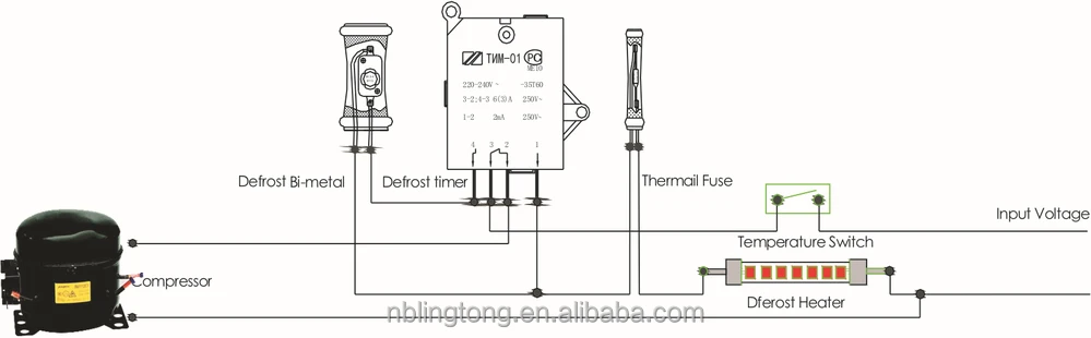
The result shows the timer can keep an figure 2 is the circuit diagram used to carry out the research at covenant university ota. 800 defrost timer wiring diagram products are offered for sale by suppliers on alibaba.com. Dtav40 series defrost timer project: To disconnect the compressor circuit and connect a resistive heating element (located near the evaporator) at permitted to operate for some length of time before the timer disconnects it from the circuit and permits the compressor to operate again.
The timer motor in this system, as in the standard feedback circuit, stops during defrost heater operation. Check circuit diagrams for 1 minute timer, 5 minute timer, 10 minute timer and 15 minute timer. 466 x 268 png 23 кб. Street light wiring diagram wiring diagram 600w inverter circuit diagram power bank circuit diagram utv about product and suppliers:
The circuit of timer motor power supply after opening of the defrost thermostat. Timer circuits ease your day to day tasks in many ways by initiating or doing it in a definite time interval.
Gallery of Defrost Timer Circuit Diagram

Ho 1119 Defrost Timer Circuits Schematic Diagram Sample And

Diagram The Defrost Timer Wiring Diagram Full Version Hd

Diagram Walk In Freezer Defrost Timer Wiring Diagram Full

Diagram Walk In Zer Defrost Timer Wiring Diagram Full

Diagram Defrost Timer Wiring Diagram Frigidaire Frs20wrh

Diagram Imc 304 Defrost Timer Wiring Diagram Full Version Hd

8145 Defrost Timer Wiring Diagram Troubleshooting Support For

Supco Defrost Timer Wiring Diagram Youtube

Precision Multiple Controls Official Website Your Source

Ll 2447 Timer Wiring Diagrams Defrost Timer 8145 20 Wiring

Diagram 8145 Defrost Timer Wiring Diagram Troubleshooting

Whirlpool Defrost Timer Wiring Diagram Gota Wiring Diagram
New Defrost Timer The Perfect Replacement Refrigerator
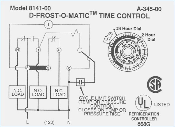
Diagram 8145 Defrost Timer Wiring Diagram Troubleshooting
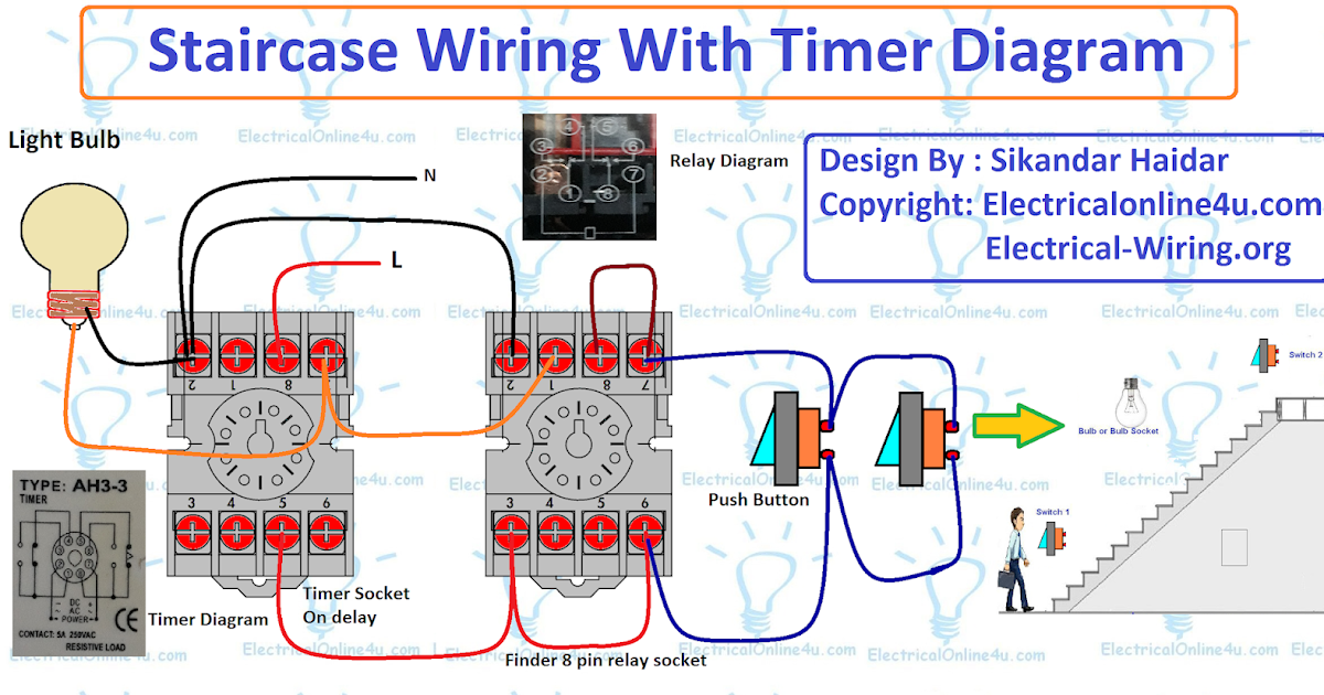
Diagram State Diagram Timer Full Version Hd Quality Diagram
Appliance411 Faq How Does A Frost Free Refrigerator S

Diagram Rapid Electric Dryer Wiring Diagram For Stand Full
