Bluetooth Transmitter And Receiver Circuit Diagram
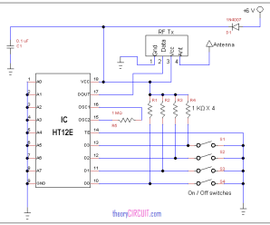
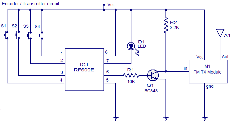
The transmitter circuit is really simple as it consists of only 4 push buttons and a transmitter.
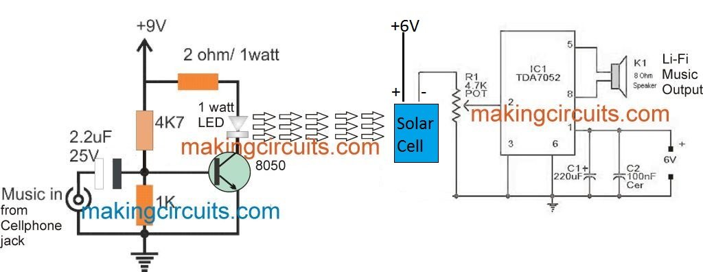
Bluetooth transmitter and receiver circuit diagram. The circuit contains microphone preamp for here is a schematic of a fm tracking transmitter circuit. 0 ratings0% found this document useful (0 votes). Arduino with rf 433mhz transmitter/receiver modules. Voice transmitter and receiver circuit.
I cant found vc1 which is available in schematic diagram but not in breadboard….and i also can't see a antenna. In this section, we'll build a simple example that wire the receiver module to another arduino by following the next schematic diagram. A wide variety of bluetooth transmitter and receiver circuit diagram options are available to you the top countries of supplier is china, from which the percentage of bluetooth transmitter and receiver circuit diagram supply is 100% respectively. Ask transmitter and receiver is used as transmitter and receiver.
In circuit diagram each pin is shown twice, you can use any one of these two sets of pins. See more ideas about receiver, circuit diagram, electronics circuit. Though it looks complex, it is as simple as the transmitter module. It comes with a rechargeable battery which needs to be changed from time to time.
- 2005 Gmc Envoy Stereo Wiring Diagram
- 2004 Chevrolet Silverado Radio Wiring Diagram
- 1999 Dodge Dakota Radio Wiring Diagram
All inductors are air cored. A circuit that can extract signals of a particular frequency from a mix of signals of different frequencies. Here we have explained the rf transmitter and receiver circuit by controlling the leds wirelessly using rf. Bluetooth is about sending and receiving radio signals between devices.
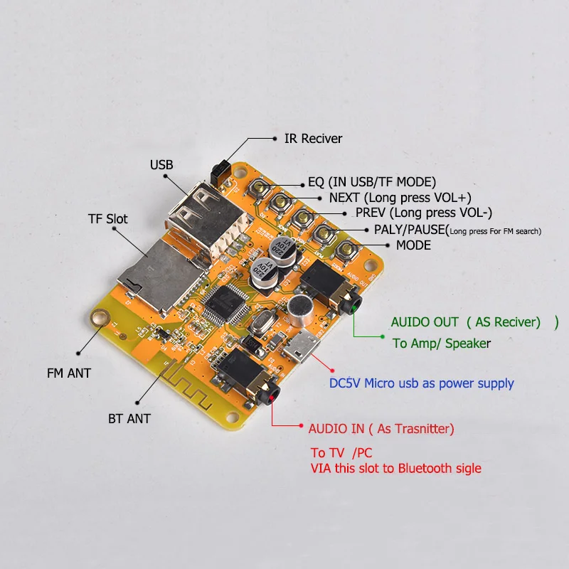
5、 bluetooth transmitter circuit board. It consists of a rf tuned circuit and a couple of. This output can be used as an indicator for the received signal strength to. A radio receiver is the opposite of a radio transmitter.
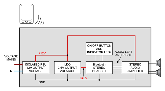
You will find the bluetooth receiver circuit box inside the device which controls the functions. Ht12e, ht12d encoders and decoders are used in this electronic circuit. Rf module transmitter and receiver circuit daigram descriptions, 3 types of rf rf transmitter receives serial data and transmits to the receiver through an antenna which is connected to the 4th pin of the transmitter. 51kω resistor will provide the necessary.
Looking for a way to tell how far you are in your garage? Transmitter and receiver module pinout. Ask rf receiver receives the data transmitted using ask rf transmitter. The proposed long range transmitter circuit really is very steady, harmonic free design which you can use with standard fm frequencies between 88 and the unit is all set up to be used for exchanging music, talks, chats across the suggested range and bands.
15 watt fm rf transmitter circuit schematics free electronic circuits diagram wiring design plans schema diy projects handbook guide tutorial 4 channel 433mhz remote control transmitter / receiver based on sm5162 and sm5172 chips circuit schematic schema wiring diagram diy project. Radio transmitters and receivers are electronic devices that manipulate electricity resulting in the transmission of useful information through the atmosphere or space. Well, then 433mhz rf transmitter and receiver modules are just for you! The ir receiver the ir receiver used was a 38 khz infrared receiver module from radioshack, but just about any will work just a well.
But i cannot see any code to upload. The rssi provides a dc voltage proportional to the peak value of the receive data signal. In the transmitter circuit it advises to then upload the code below. They can often be obtained online for less than two dollars for a pair, making them this one is a receiver module.
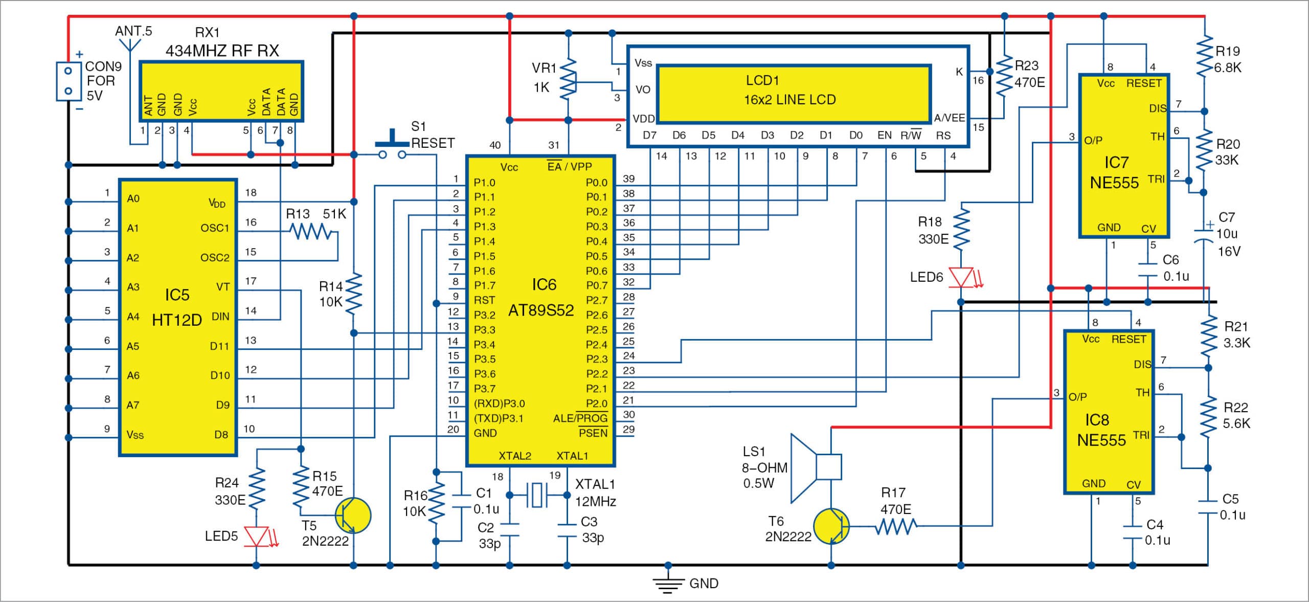
How did u make it, this circuit diagram isnt working. We have made a new diy fm transmitter kit. Set your fm receiver for a clear, blank station. The complete circuit diagram including the transmitter and receiver part for this project is shown in the images below.
But in hardware (mostly) you will have only one set of pins. Rf transmitter circuit can be safely powered from. On its own, the antenna captures radio waves of all frequencies and sends them to the rf amplifier, which dutifully amplifies them all. A transmitter consists of a precise oscillating circuit or oscillator that creates an ac carrier wave frequency.
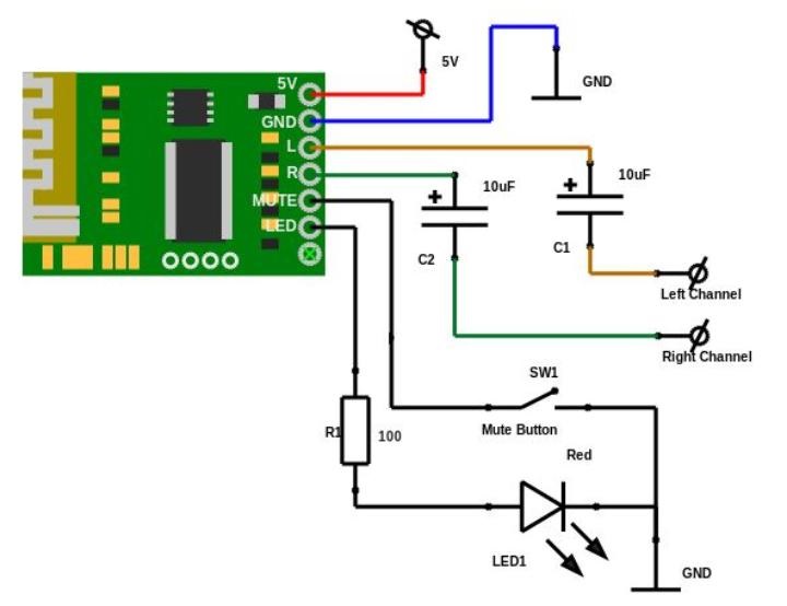
I want bluetooth headset circut. Zigbee standards are standards with a range between bluetooth and wifi. The circuit can be operated with 1.5v battery (any size) and it will last longer because the. Savesave circuit diagram of rc transmitter and receiver for later.


