Bending Moment Of Triangular Distributed Load

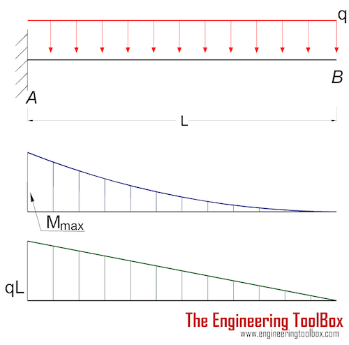
The Cantilever Beam A B Shown In The Figure Is Subjected To A

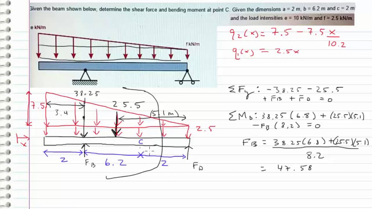
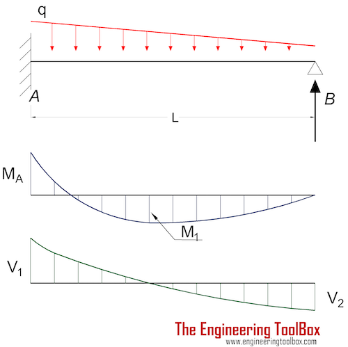
Shear Force Amp Bending Moment With Triangular Load On Beam

The Beam Supports The Triangular Distributed Load Shown Below
Solution first draw the free body diagram and solve for.
Bending moment of triangular distributed load. A cantilever beam carries a uniform distributed load of 60 kn/m as shown in figure. Case 3 is a horizontal cantilever beam ac with a triangularly distributed load from a to b. Area moment of inertia equations & calculators. The shape of bending moment diagram is parabolic in shape from b to d, d to c, and, also c to a.
A bending moment diagram is the graphical representation of the variation of he bending moment along the length we will take different cases of beams and loading for plotting s.f. Distributed load exerted over full span lengths of beam. Deflections for simple and continuous beams under different. V = v(x) and m = m(x).
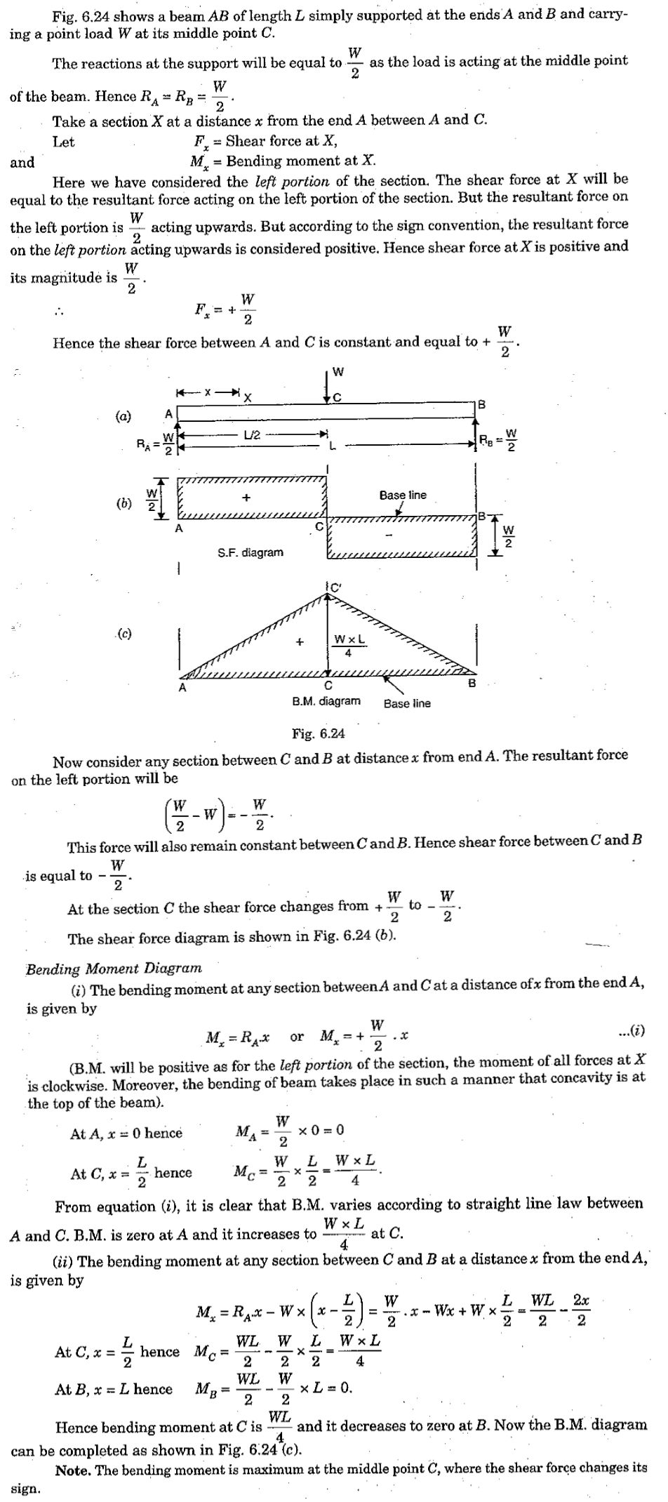
Draw the shear force diagram. Bending moments are considered positive when the moment on the left portion is clockwise and on the right anticlockwise. Shear force & bending moment with triangular load on beam. Use the same commands as shown, but with the following changes:
Bending moment refers to the internal moment that causes something to bend. Such bending moment is called a sagging bending moment or positive bending moment. Cantilever with a triangular load. Relations between distributed loads and internal shear forces and bending moments.
Moving on, the video introduces with the triangular distributed loads and briefly demonstrates how to convert a triangular distributed load into a point load. The bending moment at the point of application of the load is given by. Will be having zero ordinate from a to c, triangular from c to d and rectangular from d to b. Beam deflection, shear and stress equations and calculator for a beam supported one end, pin opposite end and triangular distributed load.
In this video triangular load has been calculated, shear force diagram. Above diagram depicts cantilever beam subjected to point load at the free end. • a distributed load can be equated with a concentrated load applied at a specific point along the bar. Draw the shear force and bending moment diagrams.
The cantilever beam has a linearly varying distributed loading, w = w(x). Join all the points up, except those that are under the uniformly distributed load (udl). Calculate the shear force v and bending moment m at the inboard end of the wing. The calculation of shear forces and bending moments in loaded beams is a common requirement in civil and structural engineering.
The total distribute load on and on each of which act through their centres of gravity. The type of loading used, whether lane loading or truck loading and whether the spans are simple or continuous, shall be the loading, which this research is concerned of studying the variation of bending moments in the longitudinal and transverse directions in the concrete slab of skew bridges. Draw the bending moment diagram. Bending moments and axial loads should be calculated using the full weight of the pile hammer, cap, and leads acting through the center of gravity of the bending moment so determined should not be less than that corresponding to a load equal to 2% of the combined weight of the hammer, cap and.
The first distributed load now appears on the model. A beam supports a triangular distributed load as shown. Design checks, hand calcs welcome to our free online bending moment and shear force diagram calculator which can generate the reactions, shear force diagrams (sfd) and. • the magnitude of the resultant force is equivalent to.
For the second distributed load select all of the elements between kp3 and kp4. Draw the shear force and bending moment diagrams for the beam. Bending moments in continuous beams caused by uniformly. In this video triangular load has been calculated, shear force diagram and bending moment diagram.
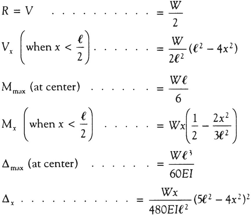
This video shows how to solve beam with triangular load. Therefore, the distributed load q(x) is statically equivalent to a concentrated load of magnitude q placed at the centroid of the area under the q(x) diagram. Unlike the udl, in a triangular distributed load the centroid position is required to determine in order to find the acting point of the converted. In probability theory and statistics, the triangular distribution is a continuous probability distribution with lower limit a, upper limit b and mode c, where a < b and a ≤ c ≤ b.
What is a distributed load? • a load applied across a length or area instead of at one point. We have already noted in eqn. This engineering statics tutorial compares a rectangular (uniformly distributed load) to a triangular distributed load.
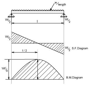
A simply supported beam of span x meters carries a udl of w per unit length over the entire span, the answer: When you bend a ruler, even though apply the forces/moments at the finally, plot the points on the bending moment diagram. Cantilever beam calculation carrying a uniformly distributed load and a concentrated load. Find the shearing force and bending moment as a function of distance along the beam:
In both cases, we need to find the. This video shows how to solve beam with triangular load. Calculate the deflection of steel, wood and other materials. Here at both ends, slope is zero means shear force is zero and also when we move from right to left, the rate of increase of shear force decreases due triangular shape of load intensity and at middle slope should be maximum and.
Conditions of loading and supports and that by using. The beam has an encastré.
Gallery of Bending Moment Of Triangular Distributed Load
Shear Force And Bending Moment Diagram For Simply Supported Beam
Statics Bending Moment And Shear Diagram Example Request
How To Calculate And Draw Shear And Bending Moment Diagrams
Cantilever Beams Moments And Deflections
Beam Formulas With Shear And Mom

Beam Fixed End Actions By Macaulay S Method Newton Excel
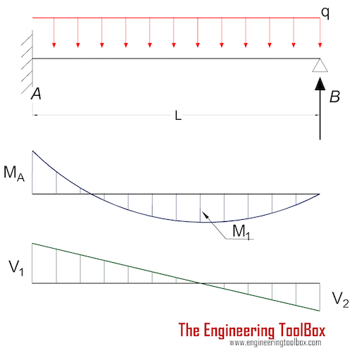
Beams Fixed At One End And Supported At The Other
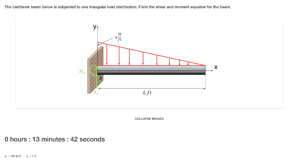
Solved The Cantilever Beam Below Is Subjected To One Tria
Simply Supported Udl Beam Formulas Bending Moment Equations

Lecture 23 And 24
Nearly Straight Cantilever Beam A Tip Load B Uniform

Sfd Amp Bmd Shear Force Amp Bending Moment Diagram

A Beam Is Subjected To A Triangular Distributed Load Whose
Beams Fixed At One End And Supported At The Other
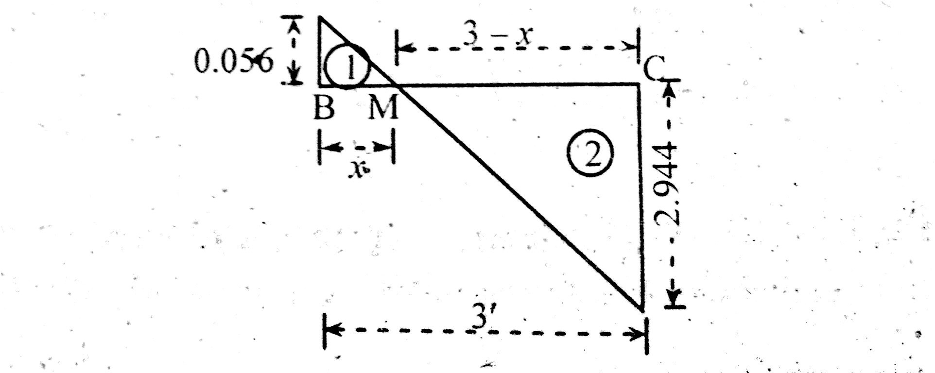
How To Locate Point Of Zero Shear Maximum Bending Moment
How To Calculate The Zero Shear Point From A Parabolic Shear

Pin On Civil Engineering
