Baldor Single Phase 230v Motor Wiring Diagram

Ls 3582 Baldor 5hp 230v Wiring Diagram Download Diagram

Diagram Baldor Motor Wiring Diagram 1 Phase Hp Full Version

Wiring Diagram Everything You Need To Know About Wiring Diagram
Wiring a baldor motor can at first glance look to be a very intimidating task.
Baldor single phase 230v motor wiring diagram. Being in the midwest, we had a lot the farm installations often didn't have access to three phase power and had to make do with single phase 230v. In this video, jamie shows you how to read a wiring diagram and the basics of hooking up an electric air compressor motor. The post discusses a single phase variable frequency drive circuit or a vfd circuit for controlling ac motor sped without affecting their operational specifications. Class h+ moisture resistant magnet wire operated at a class f rise for long insulation life.
3ø wiring diagrams diagram dd1. Motors and other similar inductive loads specifically do not like operating with frequencies that might be not within their. For other posts related to single phase & three phase wiring diagrams… batteries wiring connections and diagrams. The single phase motor are those motor which is working one phase and neutral (ground) supply for doing his duty and a 3 phase motor required 3 phase power source.
50 micro farads 450 v. With undersized wire between motor and power source the starting and load carrying capabilities of the motor will be limited. After also consulting a baldor servicing motor shop, i confirmed that macplus is correct in post #10. V/hz or sensorless vector control fort smith test facilities features • over 32,000 square feet of lab space • covered floor trenches provide easy wiring to all areas • noise hearing protection is required • dynamometers utilize baldor vector motors and regen drives.
Residential power is usually in the form of 110 to 120 volts or 220 to 240 volts. Baldor leads the motor industry in applying new technologies and materials to improve motor reliability. Yet, with the help of this step by step guide, this task will be become as easy as counting to five. Bridge l1 and l2 if speed controller (s/c) is not required.
The 11 wires suggests its a 3 phase motor, based on a variety of dual voltage wiring info on the 'net. Baldor cem3546 motor, and lenze smvector actech by connecting the ground wire on the incoming 120 v single phase to that same pe terminal, is the. Refer to the name plate data for correct connection for delta ( ) wired motors m 1~. 230v armature dc motor control single phase dc drive circuit diagram for 230v ac motor speed controller circuit diagram for 230v ac motor speed controlled wiring diagram contactor with push button diagram of dc motor drive 230v 3 phase scr firing for dc motor speed.
I need a wire diagram for a high voltage baldor motor cat # 054180 79151 connect to 440vac it's a 40hp, rpm 3525 , 3ph and it's spec#. The main or primary windings are directly connected to the power baldor motor chart [pdf], nema quick reference chart to nema frames & motor. Wiring a motor for 230 volts is the same as wiring for 220 or 240 volts. Apparent power is the power supplied to the electric circuit.
And the standard industry input and feedback make these dc specification rating wire insulation windings feedback. I have been looking all over the internet on how to wire it up to go another red wire connected to v1 and another white wire connected to w1 also lead off into the motor. Baldor single phase 230v motor wiring diagram baldor electric motor wiring diagram elegant ge electric motors. Now, for the purposes of safety, the steps listed below will only demonstrate how to wire a motor for 240v.
Narrow your search by selecting motor type, gearbox, voltage, and phase options for your desired motor. 3 wire reversible psc motor. Motor parameters are provided with the pc software making all interconnection wires between the control, ac power source, motor, host control and any operator interface stations should be in metal conduits. Most single phase motors have two sets of windings.
230v 1 phase 2 h.p. The above diagram is a complete method of single phase motor wiring with circuit breaker and contactor. How to use the motor search tool. This is a single phase 230 volt unit with a baldor motor.
Nothing is yet connected to u1. I need a wiring diagram for a hobart reversible disposer with a drum switch. Old ge single phase motor wiring diagram. Baldor servo controls are compatible with many motors from baldor and other manufacturers.
Collection of baldor single phase motor wiring diagram. I have a baldor 230 volt 3450 rpm electric motor. I have 1 8 4 5 j j wires connected 18 ,45 to power source for standard rotation, no start. Electric motor wiring diagrams & guides.
However the link below mentions a 1.5 hp motor running on 110/220 (certainly single phase). I drafted up a wiring diagram that i printed to a sticker to place on the wiring cover for future reference. 1.5 kw 1330 rpm 50 hz 9.4 amps. Power & control wiring trending.
A wiring diagram is a streamlined traditional photographic depiction. These tips can be used on most. The diagram is almost always either on a label on the side of the motor or on a label inside the little connection hatch. Wiring a motor for 230 volts is the same as wiring for 220 or 240 volts.
Description of three phase 3 phase induction motor wiring diagram. 1 phase & 3 phase wiring. Vfds and single phase ac motors.
Gallery of Baldor Single Phase 230v Motor Wiring Diagram

Diagram 5 Hp Electric Motor Single Phase Wiring Diagram

Diagram 10 Hp Baldor Motor Wiring Diagram Full Version Hd

Diagram 3 Phase Baldor Motor Wiring Diagrams Full Version Hd

Vf 2036 Phase Motor Wiring Diagrams 3 Phase Motor Wiring

Diagram Dayton Drum Switch Wiring Diagram For Electric Motor

Diagram Baldor Electric Motors Wiring Diagrams L1410t 230

Diagram Ge Motor Wiring Diagram Full Version Hd Quality

Diagram Baldor Single Phase 230v Motor Wiring Diagram Full

Baldor Reliance Industrial Motor Wiring Diagram Baldor Single

Diagram Baldor Electric Motors Wiring Diagrams L1410t 230

Hb 1056 Dual Run Capacitor Wiring Diagram On 5 Hp Baldor

Wiring Diagram Baldor 2 Hp Single Phase Motor 1972 Chevy

230v Baldor Motor Wiring Diagram Full Version Hd Quality
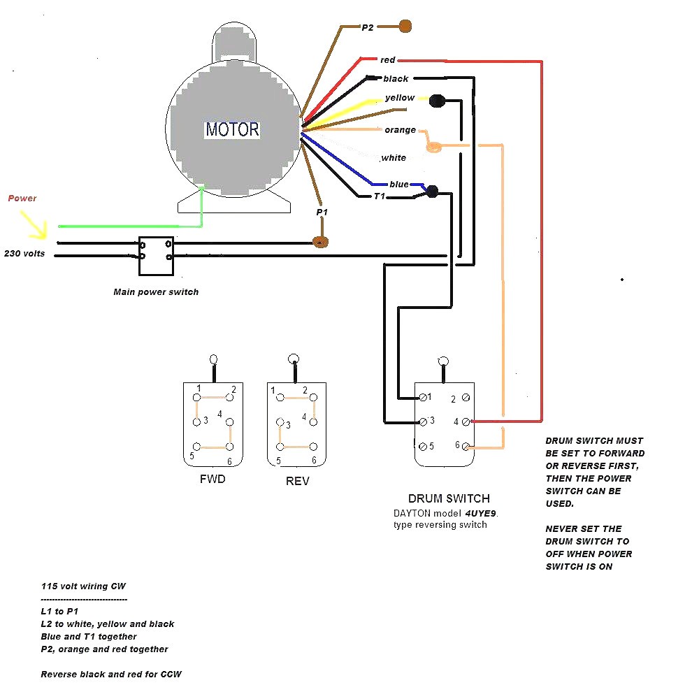
Diagram Baldor Single Phase 230v Motor Wiring Diagram Full

Diagram Baldor Motor Wiring Diagrams Single Phase Full

Need Wiring Diagram For Baldor 1hp Single Phase Motor

240v Motor Wiring Diagram Single Phase Collection Single
