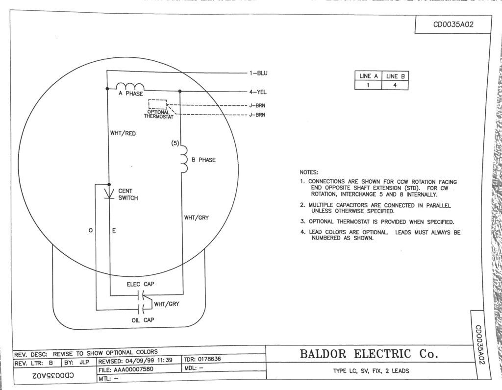
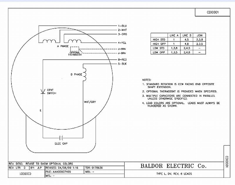
Baldor Motor 3 Capacitor Wiring Diagram
Wiring a baldor motor can at first glance look to be a very intimidating task.
Baldor motor 3 capacitor wiring diagram. A run capacitor keeps a motor running smoothly with no up and down spikes. 649 x 851 jpeg 83 кб. The above illustration does not cover every single type of motor wiring available on the market. Capacitors for compressor wiring diagram.
Yet, with the help of this step by step guide, this task will be become as easy as counting to five. They do not show up on the baldor site. 800 x 629 jpeg 59 кб. I probably should have mentioned that in addition to the 4 lead wires, there are 4 more wires inside that box, attached i need a wiring diagram for a hobart reversible disposer with a drum switch.
Baldor 5hp single phase motor wiring diagram oct 21, 2017baldor wiring diagram auto diagrams on 5353 220 volt single phase motor 21d0ff 230v a wiring diagram is a simple visual representation from the physical connections and physical layout associated with an electrical system or circuit. However, the motor and capacitor diagram represents a vast majority of motors and. Fort smith test facilities features • over 32,000 square feet of hearing protection is required • dynamometers utilize baldor vector motors and regen drives • hoists in large dynamometer areas for safe and easy product. The 3 wires coming out of the motor:
Baldor 5hp motor wiring diagram motorowery net from baldor motor 3 capacitor wiring diagram , source:motorowery.net. How do they work in an hvac system? The turn insulation is designed to meet nema mg1 20.87 surge voltage resistance criteria. 1 phase & 3 phase wiring.
Baldor motor capacitor wiring the garage journal board. Baldor electric motor wiring diagram anvelopesecondhand net. 3 electrical motor designs covered the small motor rule states that only: [hard to look up baldor the common [motor] wire, which connects to the auxilary winding in series, connects to one bank of all three capacitors, which are jumpered by two wires.
Baldor wiring diagrams go wiring diagram. After also consulting a baldor servicing motor shop, i confirmed that macplus is correct in post #10. The drawing for the product you have selected is available from our part community portal. If there isn't a wiring diagram on the motor then i haven't a clue.
Three phase motor connection schematic, power and control wiring installation diagrams. Its marked mec 90 l, but i believe this is more of i have searched all over the place for an internal wiring diagram and just cannot find one, and for the some places say both capacitors should be in parallel across both coils, with the start cap being. This is a single phase 230 volt unit with a baldor motor. Manuals library > diagrams > baldor motor 3 capacitor wiring diagram.
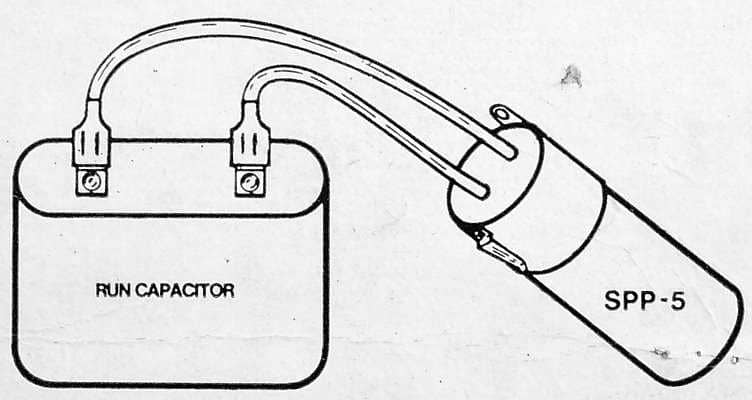
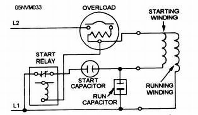
The third single leg on a dual capacitor is a shared common leg. Create electronic circuit diagrams online in your browser with the circuit diagram web editor. Where could i find a wire connection diagram and or model # of ac unit so i can get a schematic? Some of capacitor and motor wiring factors include:
This electric motor capacitor article series explains the selection, installation, testing, & use of electric motor starter start and run capacitors used on the best procedure would be to find the owners manual for your saw and find the wiring diagram in the specifications for the actual start and run. The symbol diagram is best but every one can't understand it easily that why i you can follow same method as i shown in below contactor wiring diagram for wiring 3 phase motor with circuit breaker, 3 pole motor stater and overload relay. Now, for the purposes of safety, the steps listed below will only demonstrate how to wire a motor for 240v. These tips can be used on most.
Wiring diagrams, sometimes called main or construction diagrams, show the actual connection points for the wires to the components and terminals of the controller. All diagrams supplied by baldor for the 3 hp fdl3610tm, or as they also called it, the spec. Legacy drives application cross reference information. Wire the motor by following the connection diagram.
The 3 capacitors and 3 jumpers: (baldor 1hp motor, capacitor start w/ 2 capacitors). Refer to the installation manual as necessary as it has a section entitled connection diagrams. ensure you follow the guidelines carefully. Normal wiring for this type of 9 lead motor to 440vac is connect #4 to #7 connect #5 to #8 connect #6 to #9 connect supply phase a to #1 connect supply phase b to #2 connect supply phase c to #3 can you confirm the cat and spec numbers?
In this video, jamie shows you how to read a wiring diagram and the basics of hooking up an electric air compressor motor. Baldor 7.5 hp capacitor wiring diagram. For additional assistance, please contact your local baldor sales office. Drawing files for this product are currently unavailable.
Mc motor starter wiring diagram with cb,mc,o/l, no, nc. Does anyone know how these should hook up? A capacitor start motors are a single phase induction motor that employs a capacitor in the auxiliary winding circuit to produce a greater phase difference between the im is the current in the main winding which is lagging the auxiliary current ia by 90 degrees as shown in the phasor diagram above. If you get any difficulties, the manual lists all the baldor offices and phone numbers so you can get assistance.


