Alpha One Trim Sender Wiring Diagram
The trailer button does not work but the trim button trims the out drive all of the way up to the trailer … read more.
Alpha one trim sender wiring diagram. Cap hoses and plug pump fitting holes. The trim sender wires may not have any color sleeve or if they do, one side will have a brown sleeve. It will fit all mercruiser #1 drives made from 1975 to date including alpha one, gen ii and bravo. The limit switch keeps you from over triming with the trim switch.
Efi/mpi fuel pumps with low pressure. The relay board takes 12v from the it is often better to be too long and trim afterwards, than to be too short and have to splice. Remove power trim pump hydraulic hoses. Reconnect wires to back of new switch/sender.
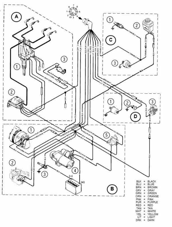
The sender is a resistance switch that works the guage. Mercruiser trim/tilt wiring for the position sender, the diagram shows one side to ground, and the other side to a brown/white wire, that goes to the connector, and on up to the trim gauge. If you ever have to have maintainance where your entire alpha 1 outdrive has to be removed (bellows for example), go ahead and install a new trim limit and sensor. Disconnect trim limit switch wires and trim position sender wires.
Alpha one trim sender wiring diagram aug 25, · re: Note that the external wiring diagram in this sensors and wiring section is entirely separate from, though there is an separate internal wiring diagram for the relay board. Most motor wire harnesses have a brown wire newer alpha gen ii's and bravo's only have one bolt and this makes life much easier. For mercruiser alpha one mr, r, tilt/trim limit limiter sensor.
Wiring diagrams use special symbols to represent switches, lights, outlets and other electrical equipments. Look on the back of the gauge and see if there is a br/w. If not change the sender. It should have the wiring schematic in it.
Alpha one gimble bellow and bearing install gen 1. Just locate the indicated wires and plug them into the gauge. If installing on boat that is equipped with merruiser stern drive, rown/white wire is connected to trim sender terminal block. Next, take a short wire and connect to sender terminal and ground terminal (shorting sender terminal to ground).
Caution steering lever ground wire must be positioned as shown or wire may fatigue. Mercruiser trim tilt sender kit alpha/bravo 805320a03. Bring together the two grommet 3. Secure the speedometer to the dashboard using the provided.
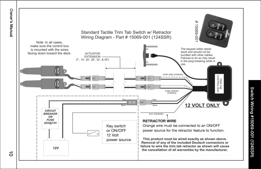
Includes mefi 3 wiring diagrams. Fault code fault text fault elimination. The diagram offers visual representation of a there are two things which are going to be present in any mercruiser trim sender wiring diagram. Disconnect the indicator leads from the terminal block on the harness plug bracket.
Also, disconnect trim sender wires at the engine harness. Trim position sender connections, mercathode connections. It cannot be used on boats which have dual station gauges, such as 1 in the cockpit & 1 more on the fly bridge. • ceramic and edp coated aluminum exhaust manifolds with temperature senders (1 sender for each manifold) connected to the pcm 555.
That the sender and limit switch are wired together and wondering if running no separate trailer tilt switch could be the issue ?? I need a wiring and hydraulic line diagram for a 1976 mercruiser trim pump. Wiring diagrams for yamaha golf carts valid wiring diagram for 2002. The trim sender leads must be connected to the brown/white and black leads.
I have a 1995 mercruiser alpha one with remote control and separate trailer and trim buttons. => page , final control diagnosis check timing. The trim limit switch installs exactly like the indicator sender. The first component is emblem that indicate.
Route new trim limit switch wires through hole. Checking camshaft adjustment check solenoid valve for camshaft adjustment: Remove the gauge's sender wire. The pointer of whatever gauge you are checking should be at the position shown in the upper portion of the diagram at right.
Connect the speedometer wires as shown in the wiring section. 50s style wiring diagram modern style wiring diagram standard style wiring diagram 50s wiring diagram modern wiring diagram standard wiring diagram ash, are you going to add the ground wires to the diagrams, as in the 50's wiring, so that remains true and accurate? P0015 16399 bank1, long term fuel trim, range 1 richness lower limit exceeded => repair group 15; Mercruiser trim sender & limit switch replacement.
Clean gimbal housing mounting flange with sandpaper and wipe.


