Activity On Node Diagram Generator
Software Engineering Critical Path Method Geeksforgeeks

What Your Boss Would Like To Know About Project Network
Activity Diagram Tutorial
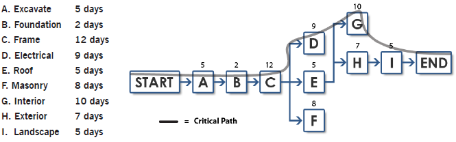
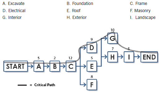
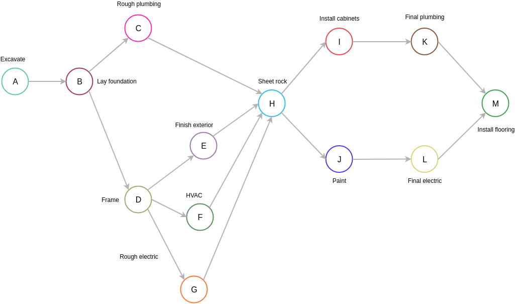
A pert chart showing activity on node (aon) diagram.
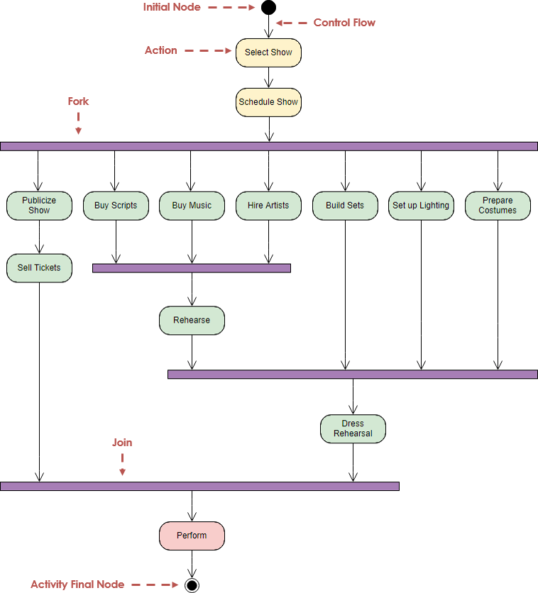
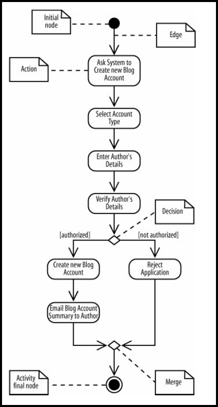
Activity on node diagram generator. This library is really customizable, you can customize nearly every part of the rendered diagram, handle events to attach behaviours on clicking on elements or other user. The most complete project management glossary for professional project managers. Activity and flow final nodes. Activity diagram in uml allows you to create an event as an activity which contains a collection of nodes joined by edges.
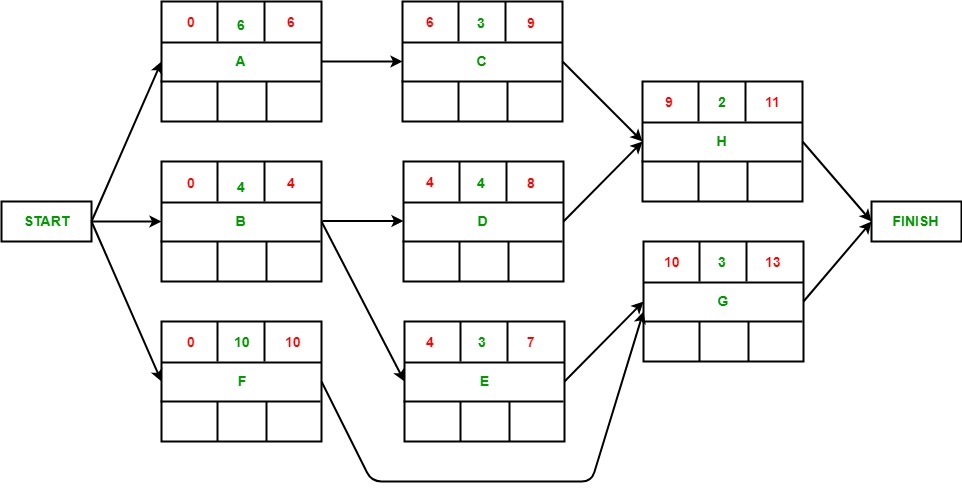
Activity diagram for a banking system. You can add one node at a time You can use quickedit for model element (see model element). Add an arrow from (activity) node i to (activity) node j if activity i must be finished before activity j can start (activity i one tip that i find useful in drawing such diagrams is to structure the positioning of the nodes (activities) so that the activities at the start of the project.
It includes activities may have more than one initial node. Learners will discover the key project scheduling techniques and procedures including; Export as image/pdf and generate java code. It is represented as a straight, slightly thicker line in an activity diagram.
- 06 Nissan Sentra Radio Wiring Diagram
- Troy Bilt Tb685ec Fuel Line Diagram
- Craftsman Lt2000 Transmission Belt
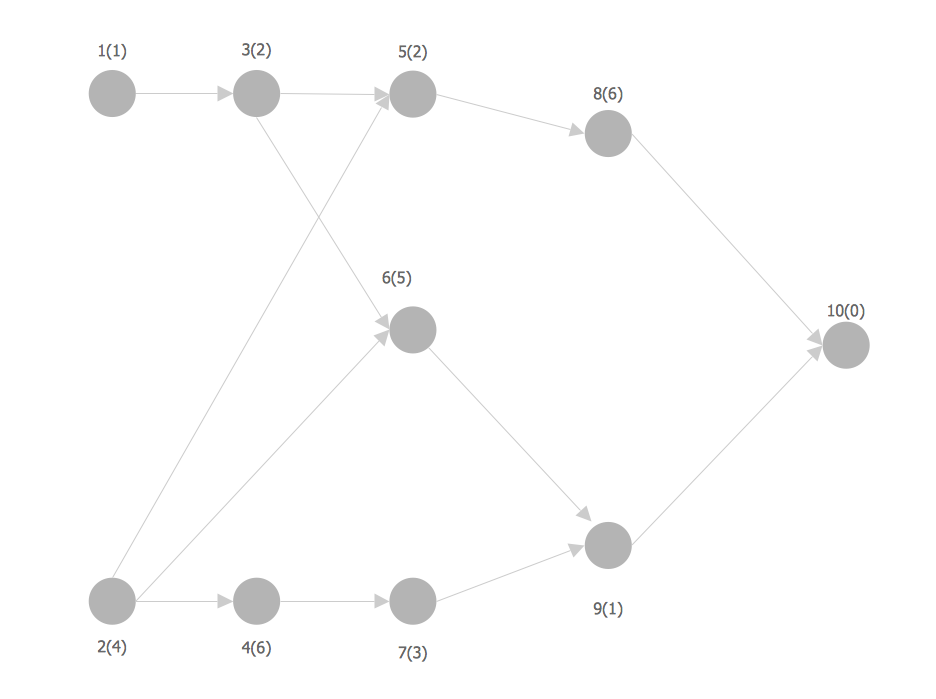
In the external view, we use activity diagrams an activity diagram can have more than one exit in the form of activity final nodes: Complete activity diagram tutorial that helps you learn about what is a activity diagram, how to create activity diagram and when. You can edit this pert chart using creately diagramming tool and include in your report/presentation/website. Additional variables can be visualised, for example, by making the node size.
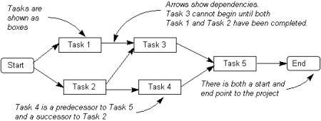
In this case, invoking the activity starts multiple flows, one at each initial node. In the example shown on the right, the letters represent project activities and the numbers on the arrows between them indicate how long it will. How to create a network diagram, how to define the importance of the critical path in a project network, and defining. Activity diagrams are created to illustrate the flow of system or business processes.
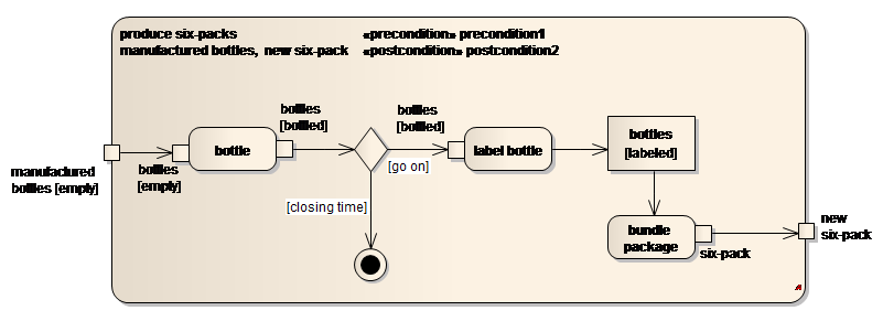
An activity diagram visually presents a series of actions and the flow of control in a system. Activity diagrams are a place where the sysml diagram frame actually has semantics; Activity diagrams include swimlanes, branching, parallel flow, control nodes, expansion nodes, and object nodes. Networkx includes many graph generator functions and facilities to read and write graphs in many formats.
Forward pass calculations determine the minimum dates at which each construction activity can. This sample shows the activity on node network diagramming method. Activity diagrams show the workflow from a start point to the finish point detailing the many decision paths that exist in the progression of events contained in the activity. If several parallel flows are present within an activity, all.
Drag on the diagram as the size of structured activity node. I think a merge node should be added before the join node because if not, the join node will wait forever. See, for example, johansson et al.2. Within the uml activity diagrams, actions belong to the activity nodes.
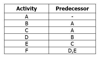
An activity diagram is a type of uml diagram. Control node is an activity node used to coordinate the flows between other nodes. The precedence diagramming method shows activity relationships. A diagram frame on an activity diagram represents the the uml activity diagram is one of the diagrams which allow the modeler to represent the behavior of an object using nodes (of activity, action.
An activity diagram may have only one initial action state, but may have any number of final action states. You can move nodes, links, create links between nodes, move and scale the viewport. Learn all about network diagrams and how to make them. To get started though we'll look at simple manipulations.
There are two types of final node: Activity diagrams as defined in the unified modeling language1 are derived from various techniques to visually illustrate workflows; The arrows connect nodes or boxes that are symbols of the start and finish of the activity in sequence. In the precedence diagram method, each node or box is an activity.
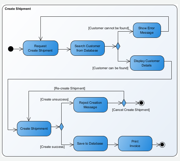
I'm learning activity diagram in uml and now i'm confused with the following diagram for representing procedures when calling a pizza. An arrow connects two boxes and shows. The activity final node is depicted as a circle with a dot inside. This diagram shows the process of either withdrawing money from or depositing money into a bank account.
The precedence diagramming method is made of rectangles, known as nodes. Project management guide on checkykey.com. These boxes show the project activities. Draw a node for each activity.
Hence, it is an important communication tool for stakeholders. However, in some network diagrams, not all of the nodes and links are created equally: And much of the basis for the definition of the activity diagram notation is found in martin and odell.3. It was created in conceptdraw diagram diagramming and vector drawing software using the seven management and planning tools solution from the management area of conceptdraw solution park.
A fork node is used to split a single incoming flow into multiple concurrent flows. If you like this video please subscribe and support us on patreon.com. Note that flows can also start at. Create activity diagrams online with genmymodel, easy uml online tool.
The graph g can be grown in several ways. An advantage of representing the workflow visually in uml is the ability to show withdrawals and deposits on one chart. Network diagrams show how things are interconnected through the use of nodes for the entities and links to represent their connections. When you use lucidchart to build.
A pdm (precedence diagramming method) chart is an example. Diagrams can be controled by the user.
Gallery of Activity On Node Diagram Generator
The Activity Network Diagram

Activity On Node Project Management Knowledge
Activity On Node Network Diagramming Tool Activity Network

Arrow Diagram An Overview Sciencedirect Topics

Activity On Arrow Diagrams
The Activity Network Diagram

What Is A Precedence Diagram Knowledge Base

Pert Templates Aoa And Aon On Creately Creately Blog
Uml From What To How With Use Case And Activity Diagram By
How To Draw A Network Diagram Using Activity On Node Method
Activity Diagram
Arrow Diagram Software
Activity Diagram Uml 2 Diagrams Uml Modeling Tool

Datastore Node Example Activity Diagram Diagram Pinterest
Project Activity Diagram Tutorialspoint
Types Of Network Diagrams Cem Solutions

3 Free Tools For Making Network Diagrams Projectmanager Com
