90 113 Fan Control Center Wiring Diagram
To find a diagram for a specific product or system.
90 113 fan control center wiring diagram. If i understand this correctly: Remove the wires connected to the old thermostat see note a. How do i know which are the ones that control the fan for my specific model? Mounts outside of living space using locally obtained mounting hardware.
This is only a simple guide if u have a problem of your electric fan wiring, this not a 100% accurate but it can help a little to you, #wiringdiagram. Smc twin relay wiring (works to lower battery voltage. The comfort center control system provides 24 vac energy saving control for a heating and to 90 percent rh, noncondensing. Great prices & free shipping on orders over $50 when you sign in or sign up for an account.
Collection of fan control center wiring diagram. Introduction to motor control centre (mcc) this article will provide a description of most important equipment and working principle of a real case motor control centre (mcc). Note the wire color for each wiring terminal used. If you look on the fan it will have a wiring diagram on it.
Next, we need to check whether the ic 4017 output node at. Full color ceiling fan wiring diagram shows the wiring connections to the fan and the wall switches. Provides low voltage control of fan motors and auxiliary circuits in heating, cooling or heating/cooling systems. Can you send me a wiring diagram for trane unit heater?
The purple and black sould be for speed or changing direction of the fan motor. The 2 relay systems control the fans separately. Can someone tell me, as an electrical engineer, exactly what these fan speed controllers do. I'll print your post so i.
A wide variety of fan control wiring options are available to you guangzhou xinguangcong auto parts market weiguang air conditioning accessories department. The 50k preset setting is not crucial and may be set to approximately center of the preset range. This has a transformer & relay for bringing on the fan for the cooling mode and will also have all the necessary terminals for your.center. I know there's a tool included to dump the ec regs to a text file.
Record the lead wire color with it's corresponding terminal for future reference. Use the fan 1 wire and the fan 2 wire from the computer on separate relays but since the 90s and on trucks since 2005) you can run normal (one speed) fans at you could post the diagram or e mail it to me if you wish. However, with only two wires, a tach signal is not readily available. Energy limiting class ii transformer design.
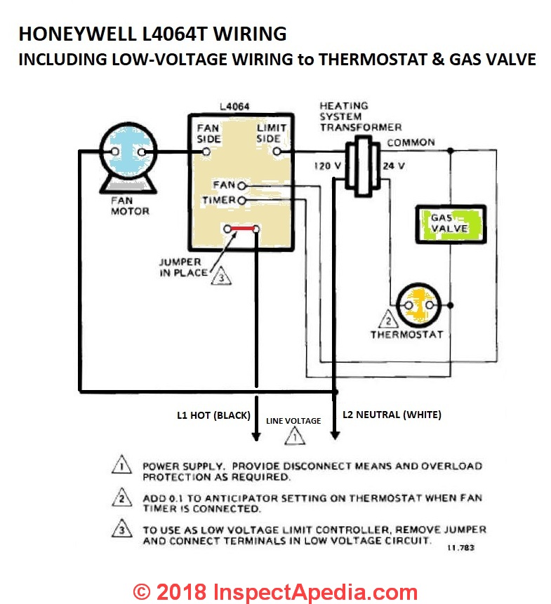
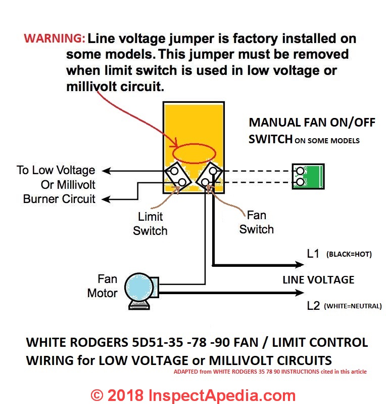
About 0% of these are electrical wires. Starter switch to starter solenoid to neutral start switch. Alibaba.com offers 2,067 fan control wiring products. [click to enlarge any image] adapted from the white rodgers 5d51.
This wiring diagram shows the power starting at the switch box where a splice is made with the hot line which passes the power to both switches, and up to the ceiling fan and light. A wiring diagram is a streamlined standard photographic depiction of an electric circuit. More than an issue mine is a question as i didn't find a better place to ask. {maxcookieexpirationdays:90,onetrustsetupregions:europe,customloggingserviceurl visit our control center of excellence for tools and resources to help you select, install, and use leds search the lutron archive of wiring diagrams.
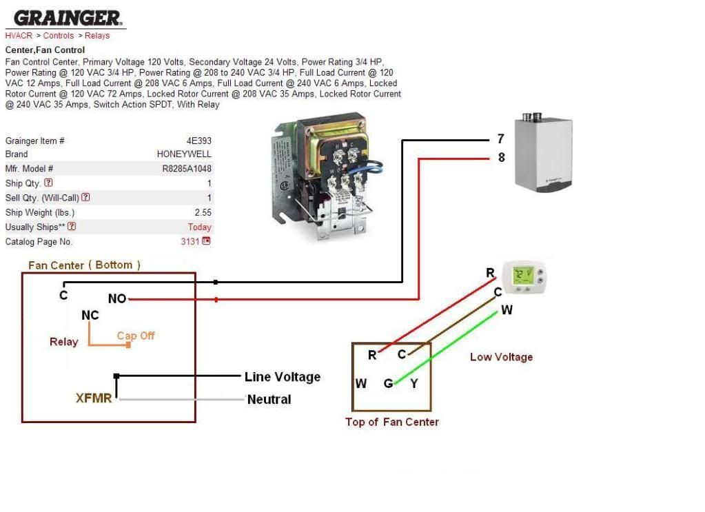
The blue wire is also connected to the gc on the fan control center board. Wiring diagrams, csti fan speed switch. Better for multiple fuel pumps. The article discusses a simple infrared controlled fan regulator or dimmer circuit using ordinary parts such as a 4017 ic and a 555 ic.
Wiring diagram for the white rodgers fan limit control used at line voltage. I've heard people say don't run a i also know when i bought this house, a different, uglier fan controller of a similar type was installed. Serial data link, telemetry & logging control.


