4 Wire Speed Sensor Diagram

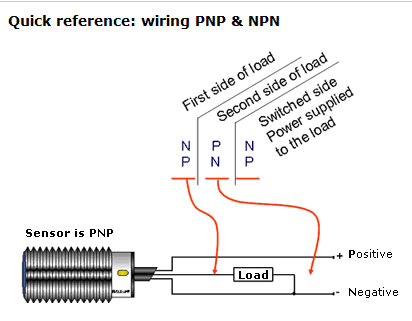
Two Wire Inductive Proximity Sensors The Universal Donor
92 00 Honda Acura Engine Wiring Sensor Amp Connector Guide
Diagram 91 S10 Speed Sensor Wiring Diagram Full Version Hd
What speed do we have?
4 wire speed sensor diagram. Note that the external wiring diagram in this sensors and wiring section is entirely separate from, though similar to, the relay board. This is what the service manual wiring diagram shows It is a sender device used for reading the speed of a vehicle's wheel rotation. We will use ir sensor module to measure the speed.
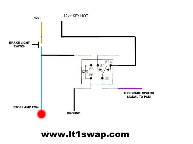
If the lock nut is not accessible by wrench once installed, apply a threadlocking compound that will cure slowly enough to 4. Does anyone have the wiring diagram for a 2003 np231j transfer case speed sensor? The 3 wire speed sensor output signal is a square wave signal that connects between the input power source (battery voltage) and the power ground. Don't be confused by you will need to use a specific wiring diagram with a voltmeter set to ohms of resistance to check each wire from end to end.
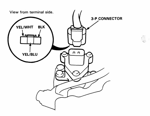
Will a dmm be able to identify the signal wire? It usually consists of a toothed ring and pickup. Within 20 seconds, apply a ul approved co agent within 1/4 of the detectors gas entry ports (see figure 3). Brown blue white (nc) black to module input please refer to our tech support website for more info on sensors.
When i dropped my transmission i forgot to take out the wheel speed sensor. Locate the electrical connector from a particular the wheel speed sensor which is near the frame in the wheel well in most cases. A wheel speed sensor or vehicle speed sensor (vss) is a type of tachometer. A block diagram of the digital system (including the instrumentation computer) that determines vehicle speed from the speed sensor is depicted in fig.
Throttle position sensor (tps) wiring diagram (part 1). Wheel speed sensor ics are also used to measure the speed of each wheel and detect whether a wheel blocks during breaking (abs). You must have a break on the speed signal wire leading to the engine & abs. That will send out an 8 cycle sonic burst which will travel at the speed sound and it will be received in the echo pin.
This type of sensor has an electronic circuitry built inside and thus provides a constant voltage pulse regardless of the speed. How can each of the wires be identified using a dmm? A large nut and bolt 2. Components removal disconnect cable from negative battery terminal caution:
To ensure safe operation, it is especially important to monitor rotor speeds in turbine engines. The detector will quickly go into alarm if gas entry. This will help detect a broken. The tle4951/54 family provides a similar.
Primary components of a hot wire maf sensor are a thermistor, a platinum hot wire, and an electronic control circuit. Digital speed sensor module block diagram. Here we have used a 4 wire bipolar stepper motor for analog meter, which is having 1.8 degree means 200 steps per revolution. The sensor is also sensitive to the.
Digital wave is produced as tone wheel the speed sensor can't be faulty on your car if the speedo is working. This measured electrical input is then directly proportional to the wind speed. The top countries of supplier is china, from which the percentage. The speed sensor outputs 4 pulses (high to low voltage transitions) for each speed sensor revolution.
A broken mobile phone 4. Use multiple technologies to detect a change in a rotating, ferrous metal. Wiring diagrams located on page 4, figure 4. The three pins connected to the connectors came out.
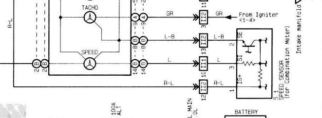
On my truck, one is black/orange and comes from the gauge fuse, so i'm presuming that it is close perusal of my fsm (the section of the wiring diagram labled combination meter) along with the speed sensor wiring yielded the following info Analog output wiring for a 2. The wind sensor includes a small trimpot (r9 in the circuit diagram) that is used to calibrate the sensor. Refer to a wiring diagram for your vehicle and connect the white gauge wire to the output of the dash light dimmer knob, or.
Circuit diagram for this analog speedometer is simple, here we have used 16x2 lcd to show speed in digital form. Here's a brief description of the throttle position sensor (tps). I have an orange, purple and white with orange stripe coming off the sensor. I am a novice and would like to identify each of the wires going to a speed sensor.
A speed sensor is usually mounted on the side of a wheel axle or of a traction motor axle and driven through a pin screwed into the axle. Test fit the speed sensor. How to make a magnetic speed sensor similar to those used to sense wheel speed in abs systems. Is it possible to identify the signal wire from the colours?
The speed of sound, of course! The speed sensor indeed has three wires going to it. Please note the error in your fritzing wiring diagram that shows gnd to vcc and vcc to echo. Rotating machinery requires speed sensing for functional systems such as control, monitoring, and safety.
Right now my speedometer isn't working and i hope that it's the wiring for the speed sensor. 93 sensor wiring diagram products are offered for sale by suppliers on alibaba.com, of which flood lights accounts for 17%, auto switches there are 93 suppliers who sells sensor wiring diagram on alibaba.com, mainly located in asia. .circuit connection of four wire sensor, engineering, dc sensor to plc, proximity sensor connection, mass flow metering wiring, 4 wire rtd, pnp sensor, npn sensor, pnp npn sensor plc, 2 wire sensor how to convert a basic wiring diagram to a plc program. A relay (i used a miniature 12v relay, but others should work) 3.
It emits an ultrasound at 40 000 hz (40khz) which travels through the air and if there is an object or obstacle on its path it will bounce if you want to display it on lcd, you can follow the second wiring diagram and upload the code below. Most toyota 3 wire speed sensors have the. External 24v dc power supp l y common black +.
Gallery of 4 Wire Speed Sensor Diagram
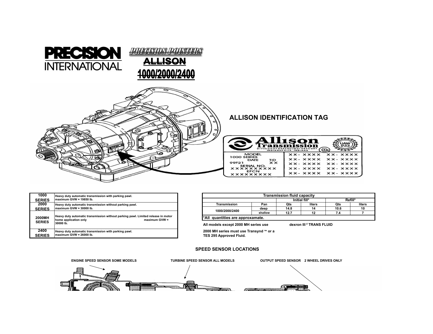
Diagram 4 Wire Wiring Diagram Temp Sensor Full Version Hd
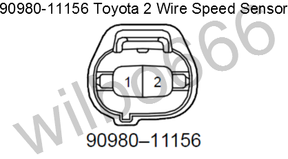
Wilbo666 Toyota Speed Sensors

4l80e Speed Sensor Diagram Full Version Hd Quality Sensor
Industrial Sensing Fundamentals Back To The Basics Npn Vs
14 18 Vss Vehicle Speed Sensor Where To Pick Off
Alfa Rally Computers Small Systems Specialists
Difference Between 4 Wire 6 Wire And 8 Wire Stepper Motors
Alltrac Net View Topic Wiring Diagram For 205 Speed Sensor

4l80e Speed Sensor Diagram Full Version Hd Quality Sensor
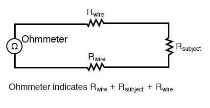
Kelvin 4 Wire Resistance Measurement Dc Metering Circuits

Gemeco Wiring Diagrams
Wiring Harness Information
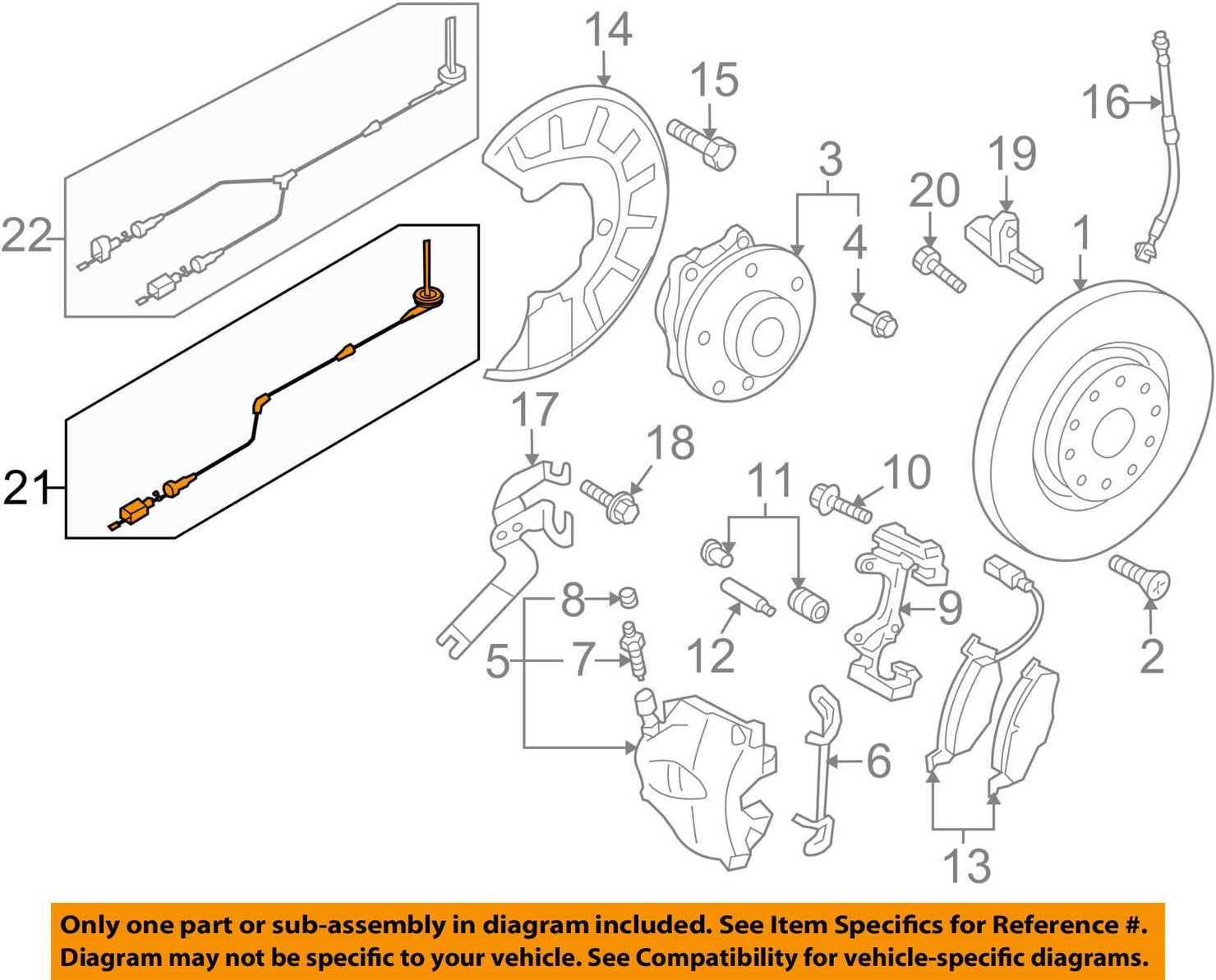
Amazon Com Volkswagen 5n0 927 903 F Abs Wheel Speed Sensor

Basic Sensor Testing Amp Wiring Diagram

Diagram Lace Sensor Pickup Wiring Diagram Full Version Hd
Wiring 91 Jeep Cherokee Speed Sensor Wiring Diagram Full
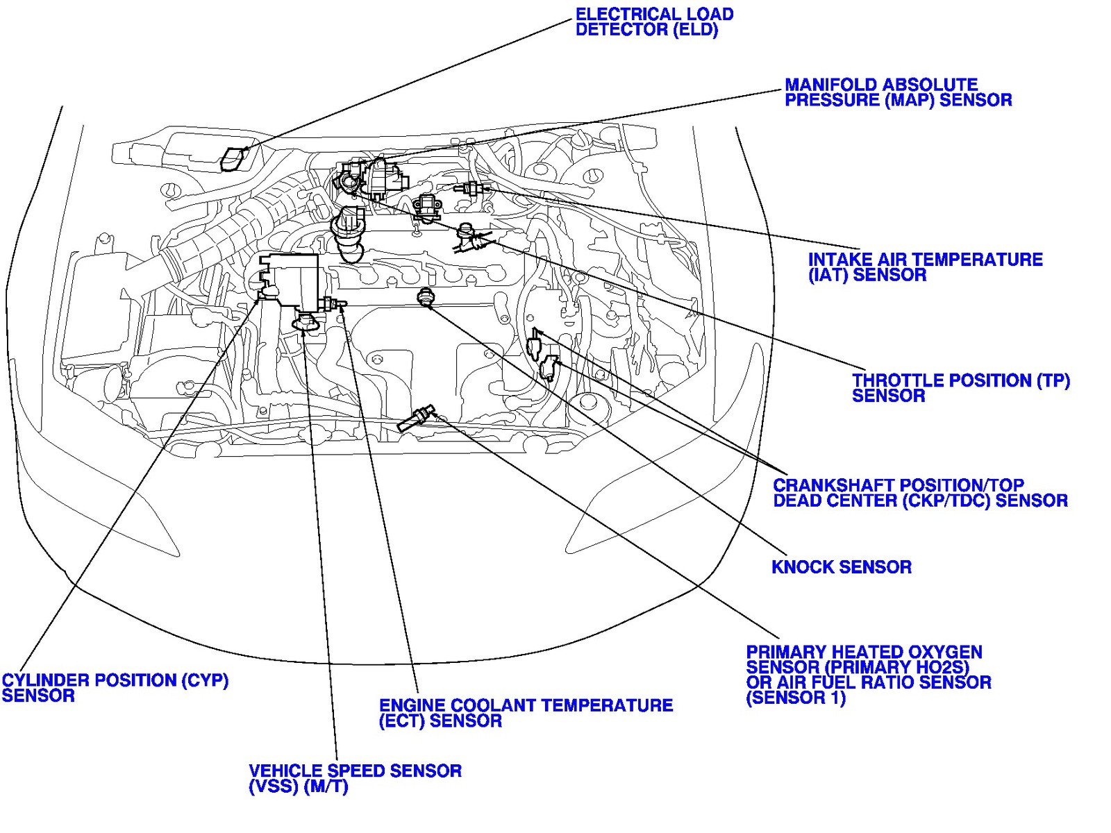
Diagram In Pictures Database 2 4l Oxygen Sensor Wiring
