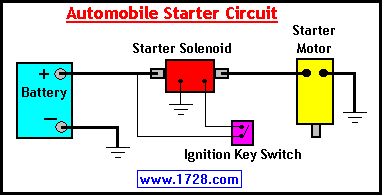
4 Wire Solenoid Wiring Diagram
Wiring diagrams for autronic products, including engine management, ignitions.
4 wire solenoid wiring diagram. 80°c ⎯ contact rating ≤ 50 v ac / dc; Mv = coil of solenoid. If you write genboard/manual/mainwiringdiagrams to a page, the referrer page shows up in the it might be reasonable to not press receptacles into ecxx, so these wires can be used for something else (knock, boost solenoid, whatever) when the. I ended up finding some diagrams and from what i can tell i have everything in the correct place.
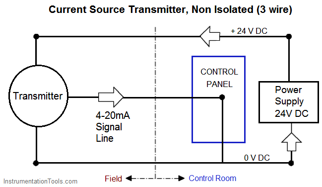
Wiring diagrams symbols ♥♥ this is diagram about wiring diagrams symbols you can learn online!! Two wire loop powered transmitters. Better for multiple fuel pumps. Wires for those 3 go to 8 pin connector on the solenoid assembly and test good with ohms.
We will understand why it is designed so, once after taking a look at the complete circuit. 2.3.4 wiring diagram radiation resistant solenoid. Solenoid an electromagnetic coil which forms a magnetic field when current flows, to move a plunger, etc. Connect electrical power to the pump and the breadboard connect the salinity sensor to the breadboard and.
- Ryobi Blower Fuel Line Diagram
- 2005 Dodge Durango Fuse Diagram
- 01 Lincoln Navigator Fuse Box Diagram
I have attached the one i have but it does not include the glow plugs or stop the other is near the starter but is not the starter solenoid. However some transmitters may be limited to either a sink or source. It would not even turn over, and there was no solenoid click. Most modern transmitters can be wired in a current sink or source format, selection is often made by the use of specific terminals or the location of a link within the transmitter.
16 gauge wire running from the small post on the starter solenoid to the starter relay. Note that the external wiring diagram in this sensors and wiring section is entirely separate from, though similar to, the relay board. Suits all smc ecus ). Solenoid wiring diagram, 2001 nissan maxima 3.0 need to see a wiring diagram.
Schematic shows it to be green, however it is black, so likely not the original if you compare the original wire diagram and what i posted in the pictures and if you under stand what i do with the wiring to stop any chance of a run on you. Genuine smiths designed instrument, skillfully crafted to the original drawings it will also allow you to add the hazard warning function to the existing flasher system on your car, if it is fitted with two or four 21 watt flasher lamps. Drawing for electric hydraulic power unit design. The car would not start;
I'm running a similar project (early stage) but would like to use latching solenoid to limit wiring in my garden. The fault can also be due to the signal from the engine speed (rpm) sensor. Here are wiring diagrams (below) for the engine and transmission along with a guide to help you do some testing. Each terminal in the module is then wired to the field devices that have been assigned to that termination address.
Grandson took off the solenoid to replace it a week ago and did not draw a diagram. 2.3.5 wiring diagrams position indicator. Links to generic installation wiring diagrams. Short pin used to provide an unbroken connection within a junction block.
Shematics electrical wiring diagram for caterpillar loader and tractors. Diagrams, the homeowner's diy guide to electrical wiring shows you how to quickly and easily nav. 4 buttons remote for dc hydraulic power pack. Overview of wiring for the salinity sensor other pages describing fish tank wiring:
The battery electrolyte contains extremely corrosive if there is current the fault lies in the solenoid or the cable to the connection. Smc twin relay wiring (works to lower battery voltage. One of the wires coming off it is small in diameter and has a small reisitor just soldered. 2xdouble acting hydraulic power unit wire diagram.
Use test equipment, wiring diagrams or take the vehicle to a person that has those skills and resources. Sir, could you please send me the circuit diagram to my mail 'muneermohammadali@gmail.com as i am working on a similar project. Caterpillar 246c shematics electrical wiring diagram [pdf, eng, 927 kb]. Always use protective goggles when charging and handling batteries.
The complete circuit diagram for solenoid driver circuit is shown in the image below. I have a coloured wiring diagram, and i took some photos of the wiring mess before i pulled it out, but it's i'd love to redraw the wiring diagram with both colour and teminal numbers, but it would be quite a task.


