4 Pole Solenoid Wiring Diagram

Ay 2879 4 Pole Starter Solenoid Wiring Diagram Schematic Wiring

673231a0 4 Pole Starter Solenoid Wiring Diagram Digital
Diagram Club Car Starter Solenoid Wiring Diagram Full
A solenoid valve is an electromechanical valve used to control the flow of fluids.
4 pole solenoid wiring diagram. Solenoids are electromagnetically driven actuators. It has a simple valve open and close mechanism operated by a solenoid. Smc twin relay wiring (works to lower battery voltage. The timer your using has a spdt switch for output.
The coil fits the solenoid and contains multiple wraps of copper magnet wire. Single pole and double pole switches are shown there are three ways to show electrical circuits. The solenoid itself is simply a coil of wire with no directional components (e.g. Better for multiple fuel pumps.
I also published 3 phase motor wiring diagram which wired with contactor. Use test equipment, wiring diagrams or take the vehicle to a person that has those skills and resources. This wiring connection is also easy as 3 phase motor wiring. In the above one phase motor wiring i first connect a 2 pole circuit breaker and after that i connect the supply to motor starter and then i do cont actor coil wiring.
- Yard Man 46 Deck Belt Diagram
- 2012 Vw Jetta Fuse Box Diagram
- 2008 Ford F250 Under Hood Fuse Box Diagram
Mv = coil of solenoid. Supplied with a wiring diagram. 3ø wiring diagrams diagram dd1. The solenoid is the tube that contains the armature and pole piece.
A three pole connector would allow how many paths of current flow? Humidistat and humidifer are connected into one wire now leaving two wires. 4 wire reversible psc motor with a triple pole double throw switch. Find out which pins are going to the you do either need a wiring diagram for that specific model from the transmission control unit to the shift solenoids i slid on road and bumped my front bumper on a street pole and i lost my forward gears…
To protect the ignition switch, lots of modern cars apply the starter relay to control the starter solenoid. The starter solenoid wiring diagram with starter relay shows in the following fig. Find a transmission wiring diagram for your transmission. Genuine smiths designed instrument, skillfully crafted to the original drawings and specifications, using the original tools and you will also need a double pole on/off switch such as 020.021 or 020.251 and a 5 watt warning light.
Electrical diagrams and schematics, electrical single line diagram, motor symbols, fuse symbols, circuit breaker symbols, generator symbols. Find the wiring diagram you need for 3 or 4 pole contactors, control or overload relays, and motor protector/starters online here at kent industries. Control a solenoid with arduino: Find solutions to your wiring diagram 4 post solenoid question.
Usually, the electrical wiring diagram of any hvac equipment can be acquired from the manufacturer of this equipment who provides the electrical wiring diagram in the user's manual (see fig.1) or sometimes on the equipment itself there are several possible ways of depicting the solenoid coil. Solenoid valves are widely used in various appliances and devices, such as washing machine, automatic irrigation system, filling machine, etc. Open and close the main power source to a piece of equipment. Ac80, ac90, ac100 single phase motors.
If b is the answer, then the right. In dahlander connection (tapped winding). Elegant 4 pole solenoid wiring diagram wiring. What is the purpose of a legend on a schematic diagram?
Solenoids and coils are used to convert electrical energy to the mechanical force used to shift valve components to control flow or pressure. Wiring diagram comes with several easy to follow wiring diagram guidelines. They are wiring, schematic, and pictorial diagrams. 4 pole control relay with 2 n.o.
We will understand why it is designed so, once after taking a look at the complete circuit. The complete circuit diagram for solenoid driver circuit is shown in the image below. 3ø wiring diagrams diagram dd3. The original poster fixed his issue when he discovered he incorrectly connected wires.
A wiring diagram is a streamlined conventional pictorial representation of an electrical circuit. Starter switch to starter solenoid to neutral start switch. Push button ignition switch wiring diagram new | wiring diagram image. Basic electrical wiring electrical wiring diagram electrical projects electronics projects yamaha xs1100 2007 mustang light switch wiring trailer wiring diagram motorcycle wiring.
Note that the external wiring diagram in this sensors and wiring section is entirely separate from, though for example, some solenoids have only one wire, and are grounded through the case, so the pulse is positive when the pole is approaching, and negative when the pole is leaving (provided. Ac80, ac90, ac100 single phase motors. T/f a solenoid valve is a device that opens or closes to control the flow of some element in a system. This arduino solenoid tutorial shows how to control a solenoid using pushbuttons and a relay with your arduino compatible controller.
Wiring diagrams for autronic products, including engine management, ignitions. As you can see the circuit is very simple and easy to build, hence we can test this using a small breadboard connection. Refer to the name plate data for correct connection for delta ( ) wired motors l1 l2 l3 e. 80°c ⎯ contact rating ≤ 50 v ac / dc;
A diode), so it can simply be reversed in the circuit to generate the maybe i am confused, but the diagram must have a flaw. Mv = coil of solenoids. 2.3.5 wiring diagrams position indicator. If the contact is broken with the relay at rest then the relay is referred to as normally open (no) and if related searches for 12 volt relay wiring diagram 4 pole 12 volt relay diagramwiring a 24 volt.
That solenoid has an inrush current draw of 4.4 amps and a holding draw of.38 amps. This should be simple with only 4 wires. 2.3.4 wiring diagram radiation resistant solenoid. 3 phase motor contactor/overload relay starter.
Suits all smc ecus ).
Gallery of 4 Pole Solenoid Wiring Diagram

Diagram 4 Pole Wiring Diagram For Trailer Full Version Hd
Tractor Wiring Theory Isavetractors
Diagram Two Pole Solenoid Wiring Diagram For Full Version Hd

Diagram 4 Pole Starter Solenoid Wiring Diagram Wiring

Cub Cadet Solenoid Questions Amp Answers With Pictures Fixya
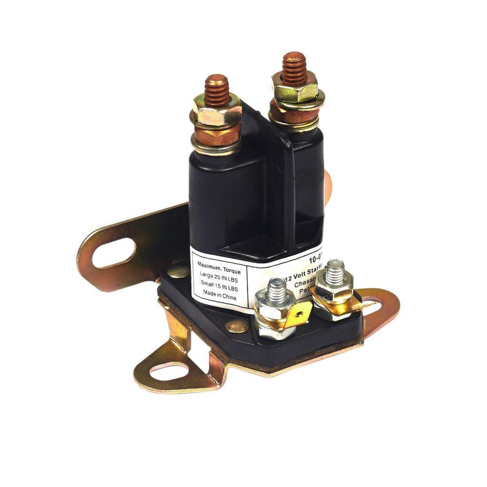
Diagram Rotary 4 Pole Wiring Diagram Full Version Hd Quality
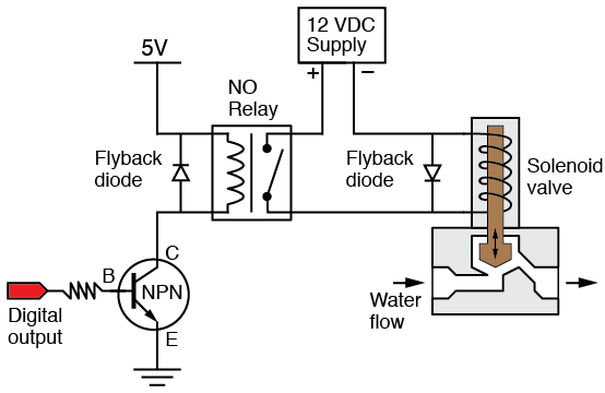
Diagram Starter Solenoid Relay Diagram Full Version Hd

Diagram 4 Pole Solenoid Wiring Diagram Full Version Hd

3 Pole Solenoid Wiring Diagram Lawn Mower Full Version Hd

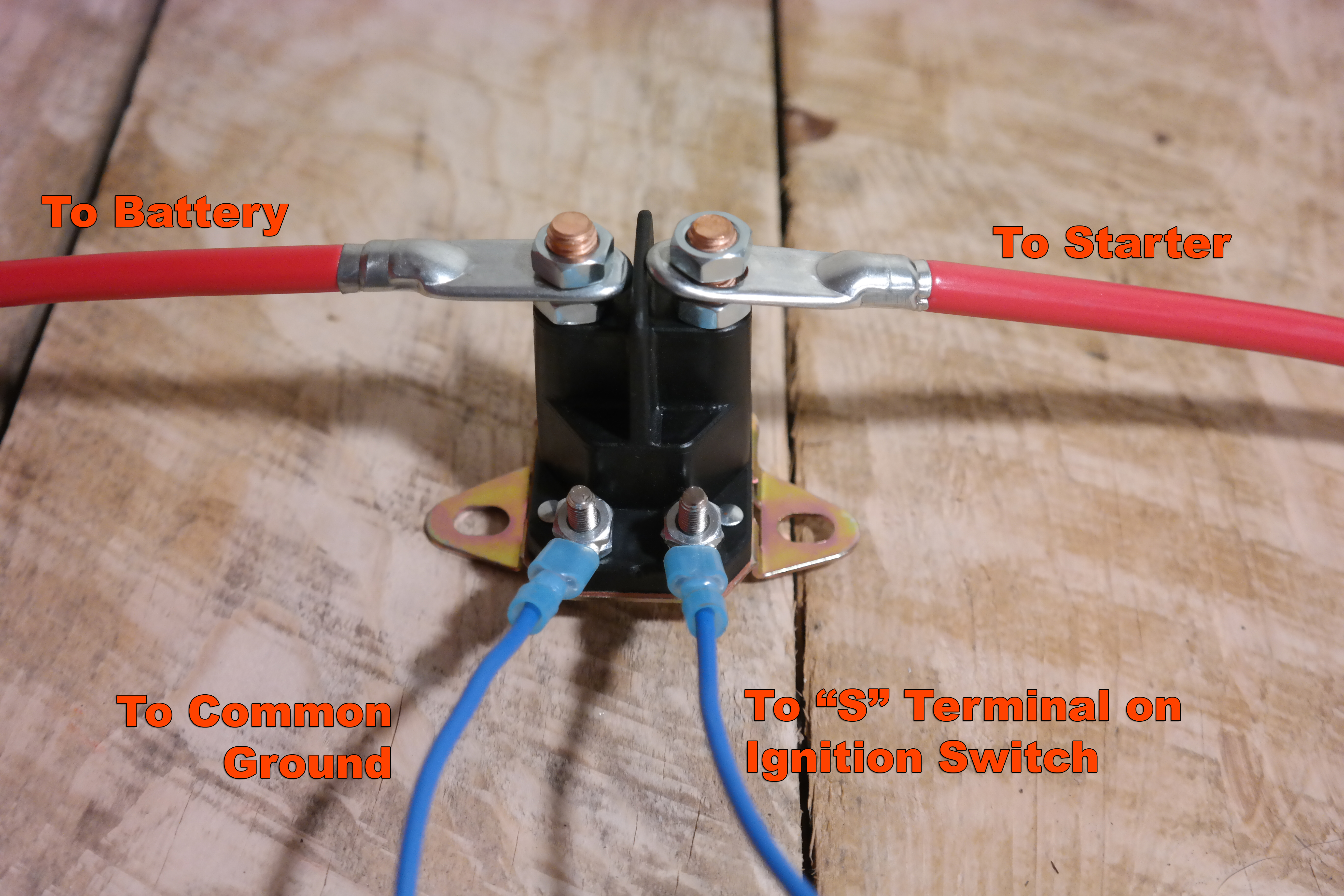
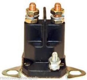
How To Wire A Solenoid Switch
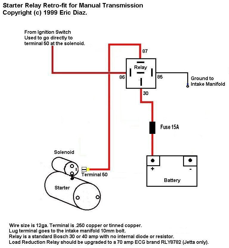
Diagram Cucv Starter Relay Wiring Diagram Full Version Hd

Diagram 3 Pole Solenoid Switch Wiring Diagram Full Version

Diagram 3 Pole Solenoid Wiring Diagram Lawn Mower Full

78e1 3 Pole Starter Solenoid Wiring Diagram Wiring Resources
Riding Lawn Mower Solenoid Wiring Diagram Gota Wiring Diagram
4 Pole Solenoid Wiring Diagram Wiring Diagram Preview
Diagram 3 Pole Solenoid Wiring Diagrams Full Version Hd
