3 Pole Solenoid Wiring Diagram
Electrically operated switch * indicates magnetic coil,motor, or thermal element.
3 pole solenoid wiring diagram. Related searches for 3 pole solenoid valve wiring diagrams 3 pole solenoid wiring. Just google search images 3 pole solenoid wiring diagrams and maybe add lawnmower or the vehicle you are working on. Safety should always be the primary consideration when wiring. As you can see the circuit is very simple and easy to build, hence we can test this using a small breadboard connection.
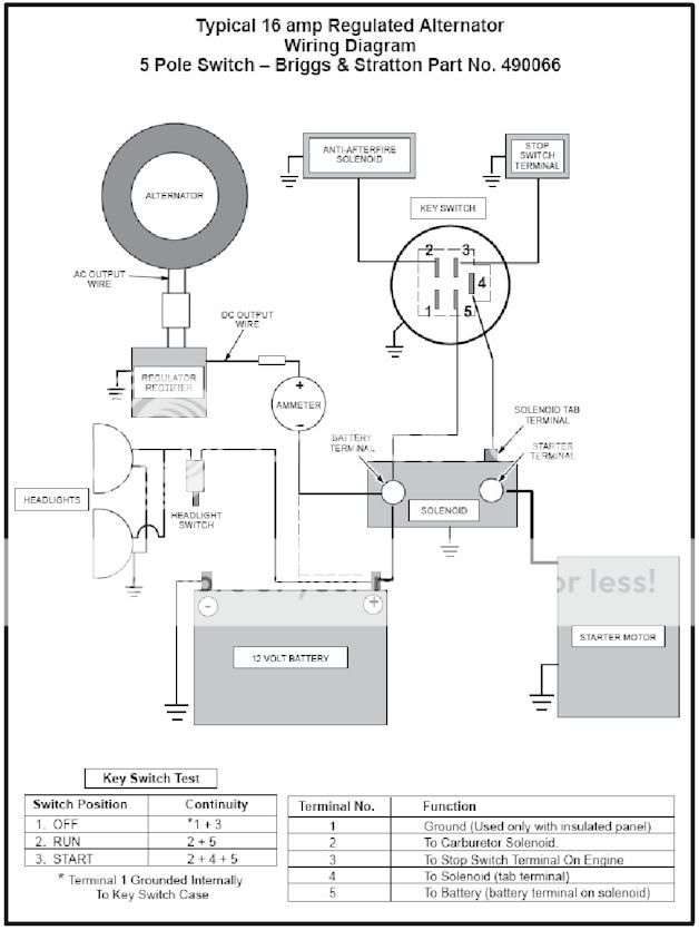
Use the proper wire size as listed by the generator set (genset) manufacturer. Multi pole single throw switch. Power & control wiring trending. Starter switch to starter solenoid to neutral start switch.
This diagram is a thumbnail. Mv = coil of solenoids. Solenoid valves are widely used in various appliances and devices, such as washing machine, automatic irrigation system, filling machine, etc. A solenoid valve is an electromechanical flow control valve used to control the flow of fluids.
1 phase & 3 phase wiring. The number of poles can be considered as the number of circuits that the switch. Notice that the wiring diagram (figure 11), uses both pictorial representations and schematic symbols. The current in three phase winding generates magnetic field of constant magnitude that rotates if the currents are ac.
4 pole control relay with 2 n.o. We will understand why it is designed so, once after taking a look at the complete circuit. Mc motor starter wiring diagram with cb,mc,o/l, no, nc. I ordered recently a 12v dc solenoid valve, a valve that's electrically controlled (*the datasheet of the valve is attached).
It reveals the parts of the circuit as streamlined forms, and the power as well as signal links between the devices. The wiring diagram provides additional engine start connection information. There are three ways to show electrical circuits. 80°c ⎯ contact rating ≤ 50 v ac / dc;
To protect the ignition switch, lots of modern cars apply the starter relay to control the starter solenoid. Electronics tutorial about the linear solenoid actuator, electromagnetic linear solenoids used as actuators and their duty cycle. Always use protective goggles when charging and handling batteries. 3 pole solenoids and 4 pole.
2.3.4 wiring diagram radiation resistant solenoid. Start date feb 1, 2017. Nitrousworks strongly recommends the use of electrical. Usually, the electrical wiring diagram of any hvac equipment can be acquired from the manufacturer of this equipment who the number of contacts (or poles):
You should search for rotating magnetic field. Single pole and double pole switches are shown, but a switch may have as many poles as it types of electrical diagrams or schematics. It will give you hundreds. I read that lead terminal c14 is my tc lockup (solenoid #3), c15 is solenoid #2 and.
A wiring diagram is a streamlined standard pictorial representation of an electrical circuit. Switch two is an old one pole switch (that i will replace with a three pole switch) with a piece of black electrical tape on the hot wire, and. For other posts related to single phase & three phase wiring diagrams… check the following useful links Multi pole double throw switch.
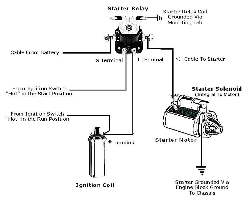
The complete circuit diagram for solenoid driver circuit is shown in the image below. I slid on road and bumped my front bumper on a street pole. The starter solenoid wiring diagram with starter relay shows in the following fig. 3 phase motor contactor/overload relay starter.
Power to switch box #1, switch box #1 to light, light to switch box #2. Solenoid valve � stop 6. 50%(2)50% found this document useful (2 votes). Related searches for 3 pole solenoid valve wiring diagrams 3 pole solenoid wiring.
Mv = coil of solenoid. Electrical wiring diagram symbols commonly found in hvac wiring diagrams learn with flashcards, games and more — for free. I became interested in controlling solenoids for robotic music applications. Apply voltage to the electrical connection i will never tried to wiring directly without enough information.
In this instructable we will be building a simple circuit that will allow us to control a solenoid using the popular physical computing platform arduino. Find solutions to your solenoid wiring diagram question. The symbol diagram is best but every one can't understand it easily that why i you can follow same method as i shown in below contactor wiring diagram for wiring 3 phase motor with circuit breaker, 3 pole motor stater and overload relay. Get free help, tips & support from top experts on solenoid wiring diagram related issues.


