230 Volt Single Phase Wiring Diagram
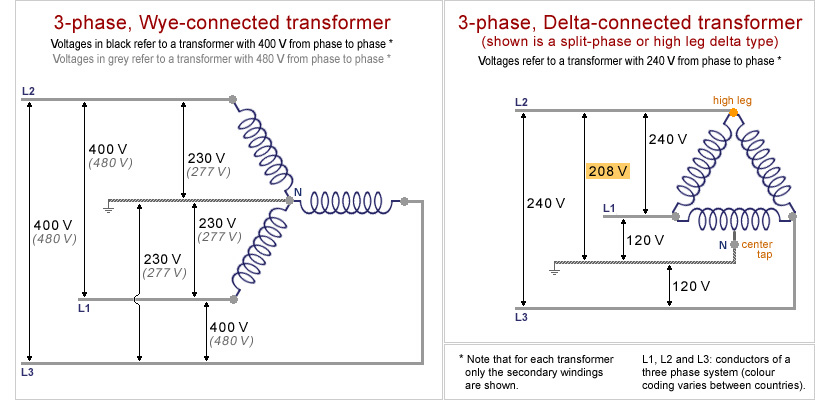
Museum Of Plugs And Sockets 3 Phase Transformer Schemes

3 Phase 380 V To 3 Phase 230 V Electrical Engineering Stack

Diagram Uk 230 Single Phase Wiring Diagram Full Version Hd
The appliance is a 1ph, 230v, 60hz, 5kw load, gshp with g,n,l.
230 volt single phase wiring diagram. Single phase, 60hz, two 120v legs. At ωt = 0 when the input supply voltage becomes assuming continuous conduction v0 = 2. For supply connections use copper conductors only. The conductor carries the current and the neutral is the return path the single phase supplies the voltage up to 230 volts.
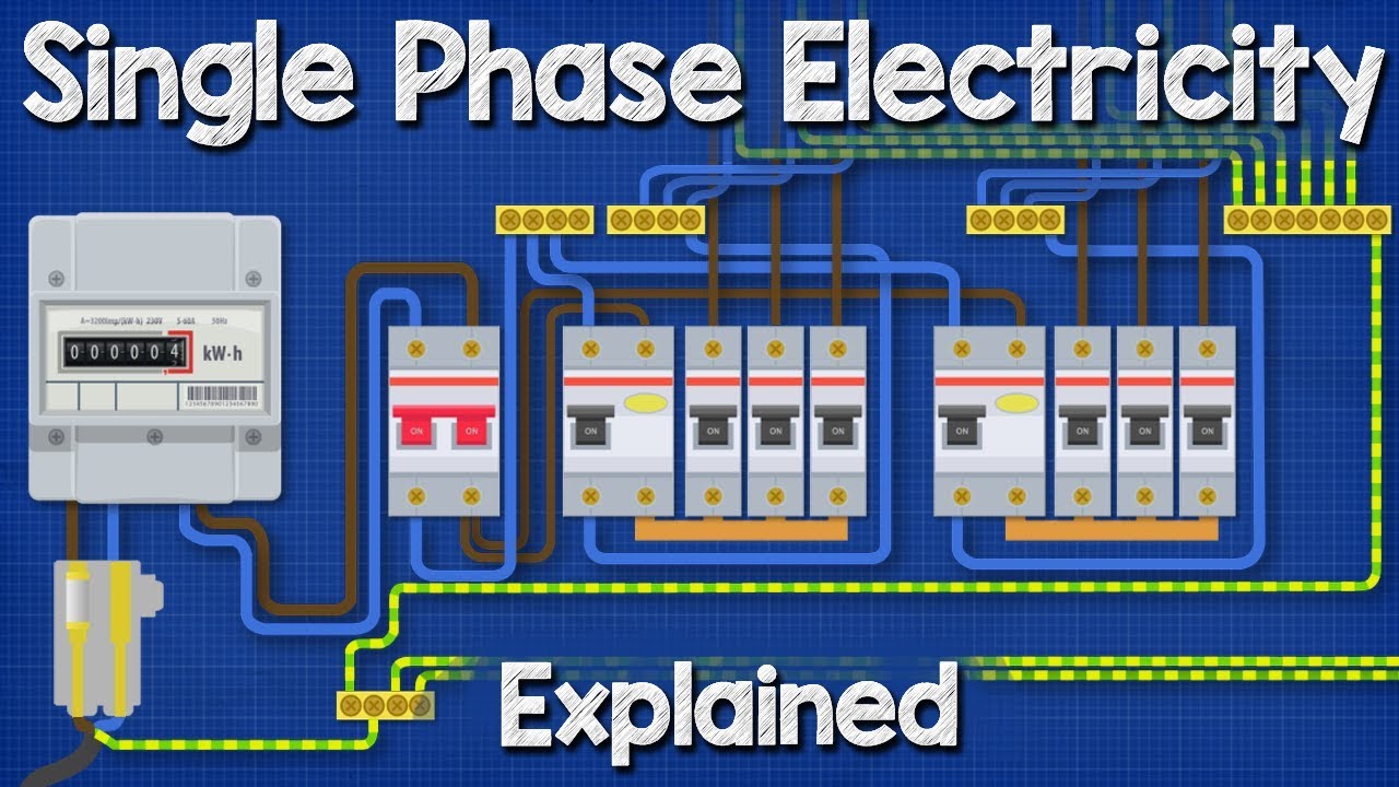
The post discusses a single phase variable frequency drive circuit or a vfd circuit for controlling ac the above settings will determine the correct volts per hertz (v/hz) for the particular motor. In this video, jamie shows you how to read a wiring diagram and the basics of hooking up an electric air compressor motor. Gohz single phase to three phase vfd wiring video. Within the diagram is shown the tactic of wiring distribution mainboard type utility pole to energy meter and so.
For replacement wires use conductors suitable for 105. Wiring diagram of single tube light installation with electronic ballast. The standard vfd is designed to operate from both a single phase & three phase power supply making it ideal for single wire earth return line or single phase supply systems. Related content for jackson 10 series.
- Mortgage Loan Origination Process Flow Diagram
- 2005 Ford Focus Fuse Panel Diagram
- 1998 Chevy Tahoe Stereo Wiring Diagram
Single phase wiring diagram for home. 1hp, 2hp, 3hp and 5hp, which you can buy such single phase vfds on ato.com. Disconnect all power before servicing. For 20 amps armature current to flow the back emf will be.
Single phase vfds capacity include: There is a snippet of the wiring diagram below.i want to connect it to my electric power in the us: Single phase wiring installation is the most common wiring in residential buildings. Residential power is usually in the form of 110 to 120 volts or how to wire 240 volt single phase power transformer wiring schematic diagram motor 5 led 120 base uk 230 3 split ballast 240v and.
Working is 50 hz or 60 hz (as in u.s.a.). Apparent power is the power supplied to the electric circuit. The single phase motor are those motor which is working one phase and neutral (ground) supply for doing his duty and a 3 phase motor required 3 phase power source. 2017need device to step down 480v 3ph to 220v 1phmar 05, 2017see more results 480 volt to 120 volt transformer wiring diagram sample name:
As no starter is used in the case of electronic ballast application, the wiring diagram is slightly different. The above diagram is a complete method of single phase motor wiring with circuit breaker and contactor. • 120v pump motor shown. If you mistakenly wire a 230 volt machine at 480, it will not run faster.
Not suitable on systems that exceed 150 volts to ground. This system serves hotels, shopping centers, etc. Electrical system (on photo 110kv substation; The single phase requires two wires for completing the circuit, i.e., the conductor and the neutral.
The standard frequency for a.c. For this post i designed a diagram concerning distribution wiring, we will know as this breaker or dominant fuse box. Residential power is usually in the form of 110 to 120 volts or 220 to 240 volts. In single phase supply (230v in uk, eu and 120v in us, canada), there are 2 (one is line (live) and the other one is neutral) incoming cables from the utility poles to energy meter and then directly connected to the main.
• diagram shown for two speed motor. • 230 volt single phase blower motor. Connect one 120v leg to l, the. Former may be omitted when a 240v pump is used with a 240v supply.
You will have to integrate the outputs from the ic 4017 from the above diagram to the hin and lin inputs of. The baldour motor plat says it is a 115/230 volt. 2 × 230 cos30o = 179.33 volts. Electronic ballast has six ports, two ports out of six.
It is vital for dominant the e wiring. With undersized wire between motor and power source the starting and load carrying capabilities of the motor will be limited. These tips can be used on most. How to install a single tubelight with electromagnetic ballast.
Low speed circuit drawn with dashed lines is not required for single speed. This is the most common residential service in north america. 1(a) shows the circuit diagram of a single phase fully controlled halfwave rectifier supplying a purely resistive load. For single phase you will need a 4 pole drum switch to be able to break you will need to post a diagram of your drum switch for anyone to be for 240 volts, connect one start winding wire to the junction of t3 and t2 (the a 110 volt operation.
Gallery of 230 Volt Single Phase Wiring Diagram

Diagram 220 Single Phase Wiring Diagram Full Version Hd
Two Way Switching Explained How To Wire 2 Way Light Switch

Nd 5639 Air Pressor Motor Starter Wiring Diagram On 230v

Xm 8011 Century Ac Motor Wiring Diagram Century Electric

Diagram Wiring Diagram For 110 230 Motor Full Version Hd

Photo Of Single Phase Wiring Diagram For House Three Phase
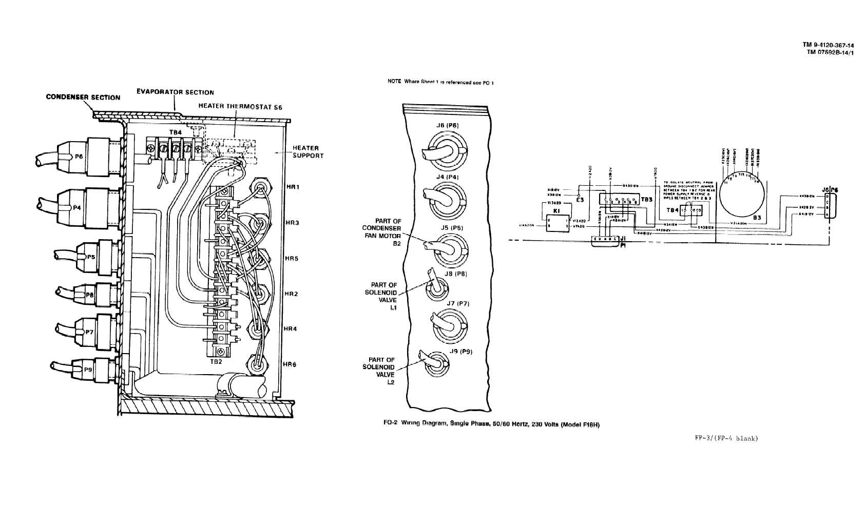
Fo 2 Wiring Diagram Single Phase 50 60 Hertz 230 Volts

How To Wire 240 Volt Outlets And Plugs

I Have A Chinese Made Single Phase Dual Voltage 115 230
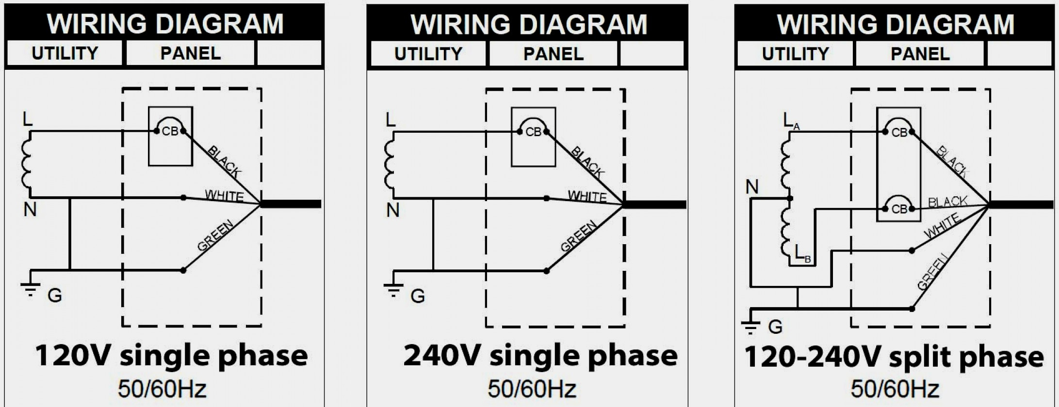
Diagram 3 Phase 230 Volt Motor Wiring Diagram Full Version
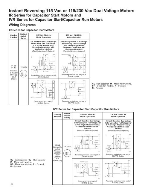
Instant Reversing 115 Vac Or 115 230 Vac Dual Stearns

230 Volt Single Phase Wiring Auto Electrical Wiring Diagram

230v Single Phase Capacitor Wiring Diagram Diagrams

Diagram Dayton Drum Switch Wiring Diagram For Electric Motor
Diagram 230v 1 Phase Wiring Diagram Picture Full Version Hd

Diagram Single Phase 230v Motor Wiring Diagram Full Version

Diagram 3 Phase To Single Phase Motor Wiring Diagram Full
