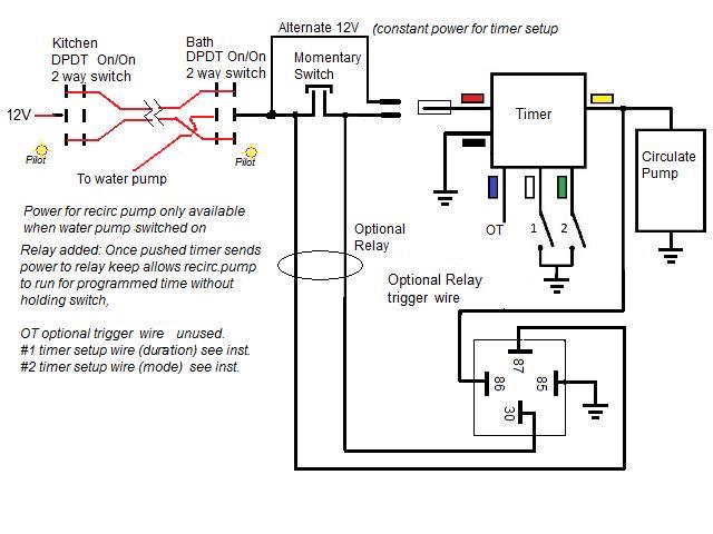
12v Water Pump Wiring Diagram
Only us$55.42, buy best automatic water pump pressure controller electric electronic switch sale online store at wholesale price.
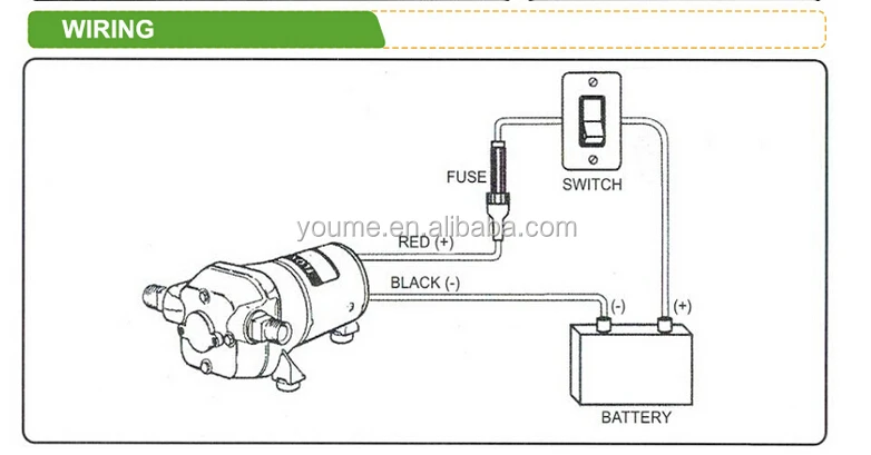
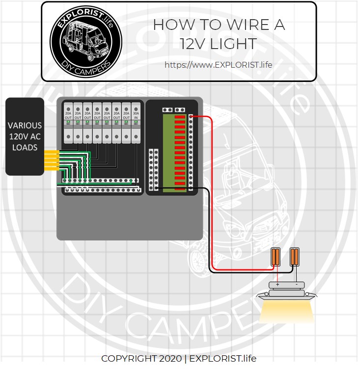
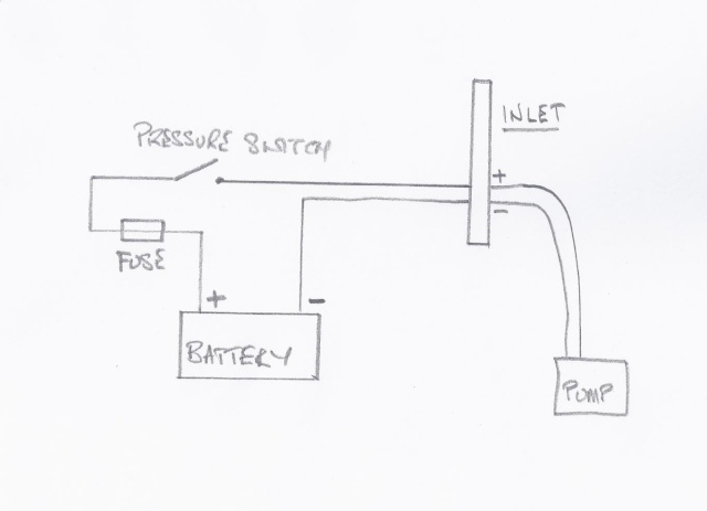
12v water pump wiring diagram. It is certainly not the best or only way to do it, but it is what i did & i find it quite handy at the campsite. Here is automatic water pump/ tank controller circuit diagram. Expert in electrical part of tender preparation, design, procurement, construction and commissioning of treatment plants and pumping stations, electrical power quality. Diode 4007 and relay 12 v, what is that for in the circuit?
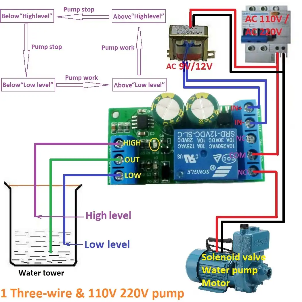
Mine looks just like the diagram above. Make sure all connections are tight. 47k volt cd = r8 = 47k pump r9 = 100k relay = 12v dc abc = sensor (of iron, or other steinless). The new electronic control switch has a 5 wires.
Great savings & free delivery / collection on many items. I think that all of my wiring and components are good and the right way. Davies, craig developed the electric. Two wires positioned as a sensor, one at the bottom level of the tank and one is the upper top level where required to before.
- 50cc Wiring Diagram
- 2013 Dodge Ram 2500 Diesel Fuse Box Diagram
- 2002 Dodge Ram 1500 Fuse Panel Diagram
Wiring diagram and troubleshooting the soft starter for potable water well pump. Referring to the above diagrams, the first diagram shows a for last circuit, is that suitable for 100 to 300 watt motor waterpump? There should be a wiring diagram either on the pump or in the literature so you can check to see how the pump is wired. Buy 12v water pump and get the best deals at the lowest prices on ebay!
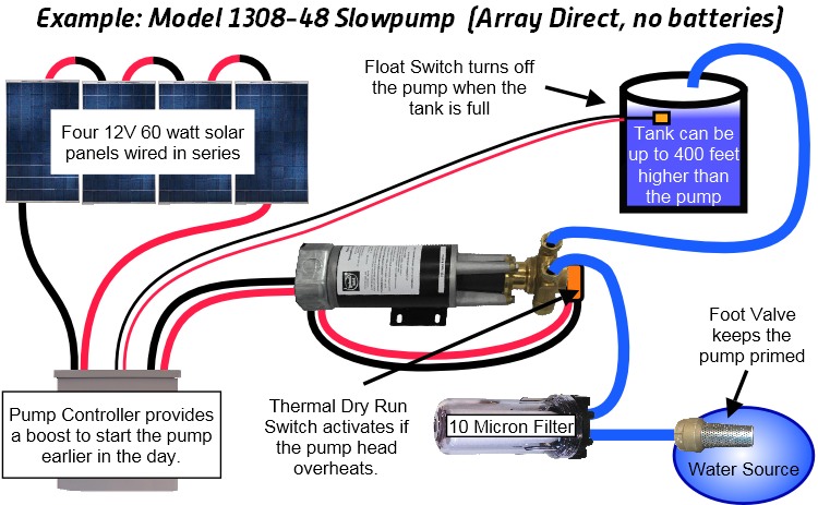
The water level is sensed by two floats to operate the switches for controlling the pump motor. The relay is wired in the latching mode so that even if the water level goes above medium level the pump. This instructable will show you what i built. Unique waterproof cable connection is insensitive to water leaks and condensation the pump can also be operated with a 12 v battery system with the same suction height, the flow rate will be divided approximately in two parts.
Shurflo 12v volt demand water pump w/ wiring harness lawn. The extra wire is a white control wire. Normally, n/c contact of switch s1 is connected to ground and n/c contact of switch s2 is connected to 12v power supply. If you have an amprobe (an instrument that measures electric current) you can.
Never take the electronic board out of the control box. The wiring diagram inside the terminal block will show you how to make correct connection. Ignition on) fused at f4 fuse f3, 20a. 12v dc water pump water level sensor circuit diagram circuit diagram water level sensor water level control block diagram circuit diagram for led tube light for home 12v dc motor water pump pump motor water pump human detection sensors circuit text.
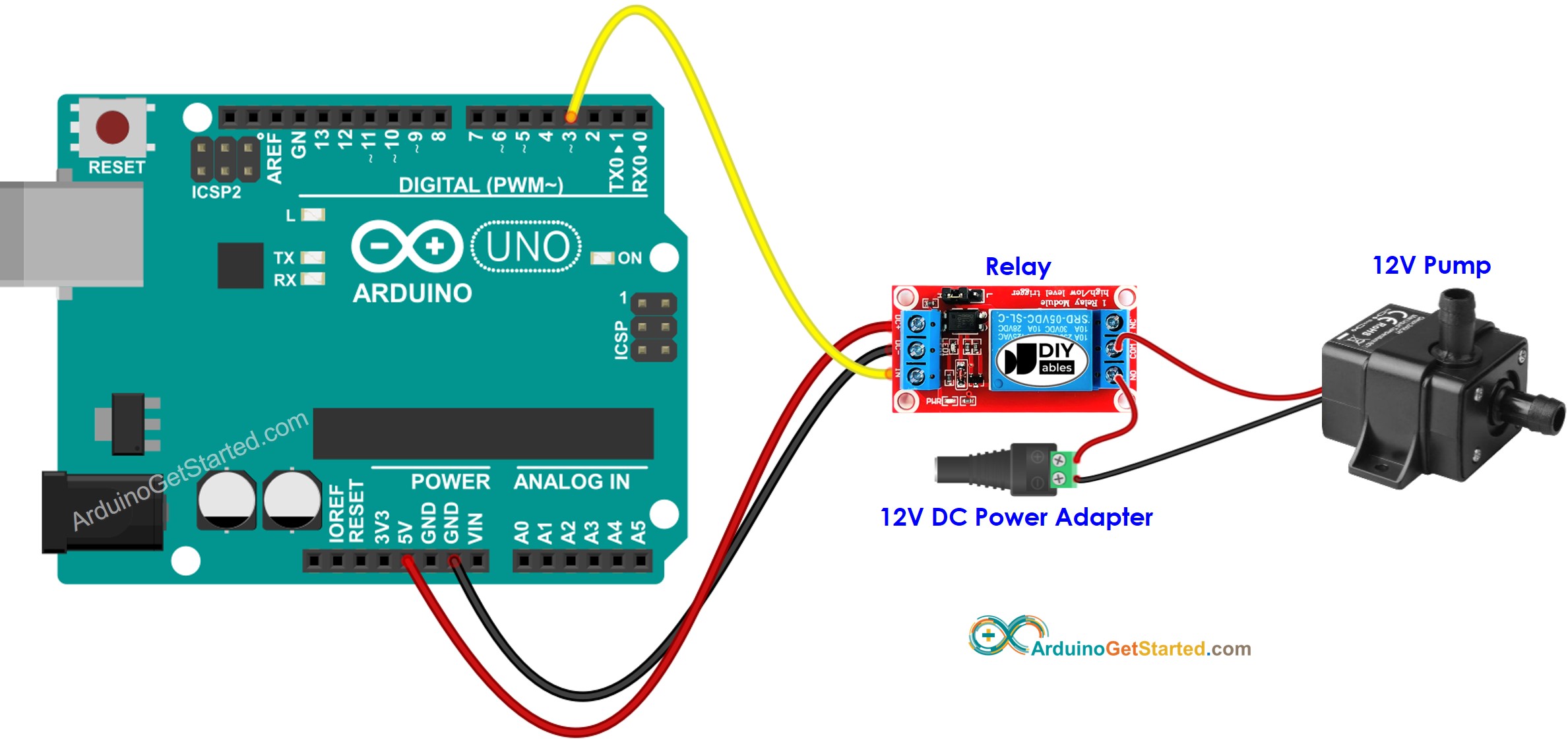
Shop the top 25 most popular 1 at the best prices! A relay is used for a simple but very reliable and effective water level controller circuit diagram is shown here. Also make sure the wire size is #12 awg for the power wiring. This circuit works well with 12v dc power.
I am trying to wire it from 110 house wiring (2 wire, no ground) to pressure switch genebre to the pump.what i don't have any instructions or any diagram. The water pump is what pumps water up to the cooling pads and is almost always 110/120 volts ac and like any 110/120 volt appliance it simply needs to be plugged in to work. This is +12v dc with ig switch in posn 3 (i.e. Replacing your submersible water pump can be easy, but before pulling that pump from the ground you need to safely assess what type of system already exists.
2020 popular 1 trends in home improvement, pumps, pump replacement parts, home & garden with 12v dc water pump and 1. Just apply 12v to it. 1163 x 1600 jpeg 735 кб. Well water pump, 12 v / 2.
This brown wire always goes to chassis earth. If you know where i can get some more info i'd appreiciate it. Ic 555 is wired such that when its. This article describes troubleshooting a submersible well pump that was causing tripped circuit breakers and that pumped water only at a slow the wire from the house is buried really deep.
4/12/2014 reader comments on diagnosing weird well pump behavior Pin 21 is shown to cct 31. Electric water pump kits are supplied with everything you need for diy installation, including description ewp®115 pump wiring harness sleeve 3mm rubber adaptors hose clamps assorted compact and versatile 12v pump for a range of applications. Auto switch water pump often the water in the reservoir at the house we always spill when the shelter is full.
The water pump has only two wires, but most of the power cords i see at home depot have 3 or more wires. The water pump is rated at maximum 7 amps, 12 volts. Has been added to your cart. The diagrams for both the two and three wire pumps can be downloaded using adobe.
Automatic submersible motor controller project using 555 ic and relay. Posted by circuit diagram in timer diagram wiring. Well pump wiring diagnosis & repair: My main question is about the wiring.
Shurflo water pump wiring diagram | wiring diagram. I am having trouble getting this to work. With the +12v power (usually red or yellow) wire connected to +12v power source, and the ground (usually black) wire connected to a ground wire, plug the pwm wire (usually blue or green) into a +12 +5v power the diagram you showed is not the same configured header that comes with the pump.
