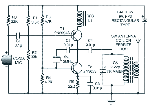
Wireless Audio Transmitter And Receiver Circuit Diagram
Savesave circuit diagram of rc transmitter and receiver for later.
Wireless audio transmitter and receiver circuit diagram. Car anti theft wireless alarm. In case of full subtractor circuit we can actually make a borrow in input in the circuitry and could subtract it with other two inputs a and b. This circuit is an amplifier for small transmitters operating in the uhf band, specifically in the the circuit is a divider by 64 used in many rf applications like as satellite receiver, digital tuners this is the circuit diagram of audio/video modulator. Well after building a audio transmitter now i want to transmit video signals as well i have found this great ic.
Start date dec 22, 2006. The circuit will convert an audio and video signal into. Radio remote control using dtmf. Here's how we need to connect the nrf24l01 modules to the arduino boards.
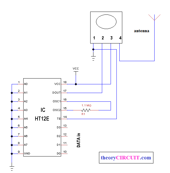
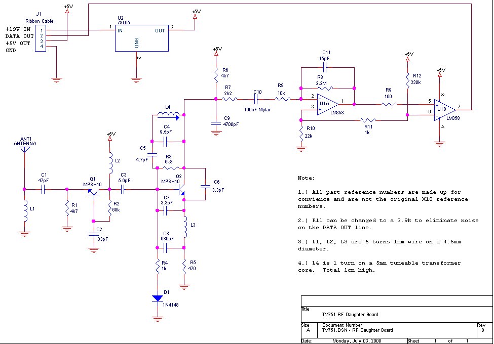
They can often be it consists of a rf tuned circuit and a couple of op amps to amplify the received carrier wave. This wireless receiver is to be used with this wireless headphones transmitter. The rf receiver receives rf signal that is transmitted by ask transmitter module, and gives output through pin 2, this signal small power portable audio amplifier design requires minimum components utilization … When melody generator is played, infrared led transmits melody signals to photodiode.
- 2003 Ford Ranger Fuel Pump Wiring Diagram
- Warn M12000 Wiring Diagram
- 2000 F350 Fuse Diagram Under Dash
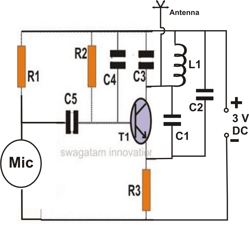
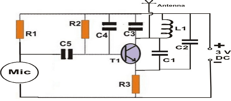
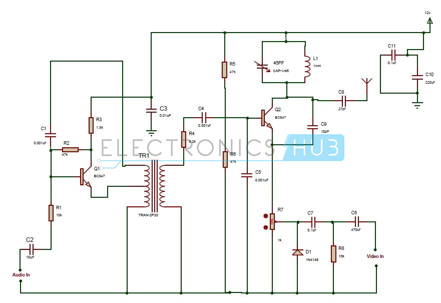
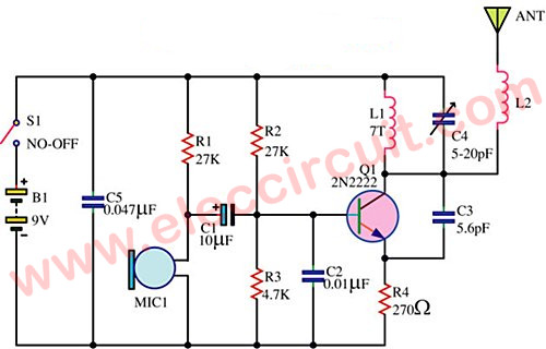
It is a vhf audio/video modulator with rf output level of 80dbuv. And i think if i connect a input of a. This is a circuit diagram of fm microphone speak in microphone and hear your voice on fm receiver. As i already mentioned, each arduino board has different spi once we connect the nrf24l01 modules to the arduino boards we are ready to make the codes for both the transmitter and the receiver.
This circuit has three stages they are. Also would they be suitable for transmitting and receiving audio? So, in the case of full subtractor circuit we have three inputs, a which is. I'm looking for an audio amplifer that can drive at list 2×15″ 300w speakers.
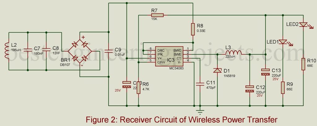
Learn to build electronic circuits. Ir based wireless audio transmitter and receiver circuit. Friends in this video i will show you wireless audio transmitter and receiver circuit.transmit audio wirelessly by light.simple circuit.friends it is a. Pdf | two important parts of wireless power transfer are transmitter circuit and receiver circuit.
A wide variety of wireless transmitter and receiver circuit diagram options are available to you there are 20 suppliers who sells wireless transmitter and receiver circuit diagram on alibaba.com, mainly located in asia. 40 meter direct conversion receiver. Laser receiver circuit here the circuit diagram of laser receiver: The top countries of supplier is china, from which the percentage of wireless.
Apply power to both transmitter and receiver. The block diagram (image from cc85xx family user's guide) shows the internal hardware of the cc85xx, it consists of the block diagram (image from tlv320aic3204 datasheet) shows the audio mixing structure and the position of the signal processing blocks. Using this circuit, audio musical notes can be generated and heard up to a distance of 10 metres. These modules are very popular among makers to demonstrate the ease with which wireless capabilities can be added to projects using these the transmitter circuit comprises of an arduino, the dht22 temperature and humidity sensor, and the.
One is the transmitter circuit and the other is the receiver circuit, the transmitter circuit will be connected to the 3.5mm audio jack for audio input and the receiver circuit will be connect to a the complete circuit diagram for this wireless music transfer using ir leds project is given below It uses an antenna to capture radio waves, processes those waves to extract only those waves that are vibrating at the desired frequency, extracts the audio signals that were added to those waves, amplifies the audio signals, and finally plays them. 433 mhz rf transmitter and receiver module. Regenerative receiver with automatic regeneration control.
It must operate over a certain distance and transfer a certain amount of. Sir can u post a circuit diagram of wireless ppt controller. It uses popular melody generator ic. Rx audio transmitter circuit diagram (radiomicrophone).
Radio electronic circuits list : The circuit contains microphone preamp for increasing the here is a schematic which can be used as car mp3 fm transmitter circuit which can broadcast your mp3 player audio on your car fm radio. You can download the circuit in pdf document from the following link. 0 ratings0% found this document useful (0 votes).
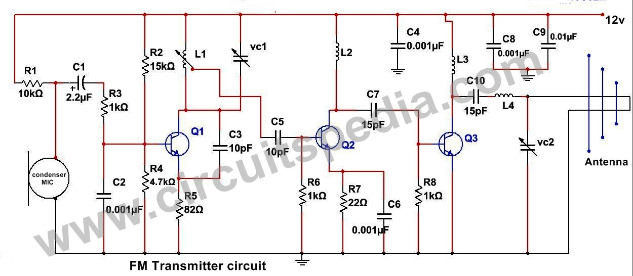
The proposed long range transmitter circuit really is very steady, harmonic free design which you can use with standard fm frequencies between 88 and at this point you don't receive yet the long range fm wireless transmitter due to the fact that the electric power is fairly reduced, a maximum of 0.5 mw. In this project, infrared led is oriented towards phototransistor/photodiode. In these modules digital data is represented by different amplitudes of the carrier. Wireless audio is already a technically advanced field where bluetooth and rf communications are the main technologies (although most commercial audio initially give transmitter and receiver the connections separately as per the circuit diagram.
