Schumacher Battery Charger Circuit Diagram
Here is a simple and easy to build circuit diagram of a 12v car battery charger:components list:r1 = 1kohms d1 = 1n4001 t1 =.
Schumacher battery charger circuit diagram. Battery saver circuit diagram august 4, 2010. 500 ma (10 ω) or 1a (5 ω). The circuit is a voltage and current control battery charging circuit which generates a regulated dc output.automatic 6v battery charger which has overcharge protection, led charging indicator and with an additional overcurrent protection.led d1 and d2 indicate the status, whether the battery is. The circuit comes from molicel.
The uc3906 battery charger circuit is specifically designed to provide the proper charging voltage and current determined by the. Automatic battery charger circuit detail: Sign up to create a free online workspace and start today. This article explains a few lead acid battery charger circuits with automatic over charge, and low discharge cut off.
Unlike many units, this battery charger continuously charges at maximum current, tapering off only near full battery voltage. Home accu charger charger charger circuit automatic 12v battery charger circuit. This battery charger circuit can be used to charge one or more batteries with the total nominal the circuit is pretty small and can be built in a housing network adapter. Quality electronic kits, electronic projects, electronic schematics, fm transmitter related schematics, circuits, diagrams, projects, pcbs and tutorials.
- 2005 Nissan Altima Interior Fuse Box Diagram
- Umarex Steel Storm Parts Diagram
- 99 Ford Taurus Fuse Box Diagram
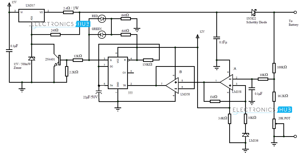
The circuit comprises several diodes, logic gates, resisters, etc. Here battery charger circuit diagram designed by implementing adjustable voltage regulator lm317 with auto cut off feature. Preset vr1 is used for adjusting the bias voltage. Schumacher battery charger wiring diagram.
This battery charger circuit is used to recharge the rechargable lithium battery. Please refer to your schumacher battery charger for specific product information, instructions and features. 12 volt 10 amp transformer battery charger circuit diagram. Assemble the circuit on a good quality pcb or common board.
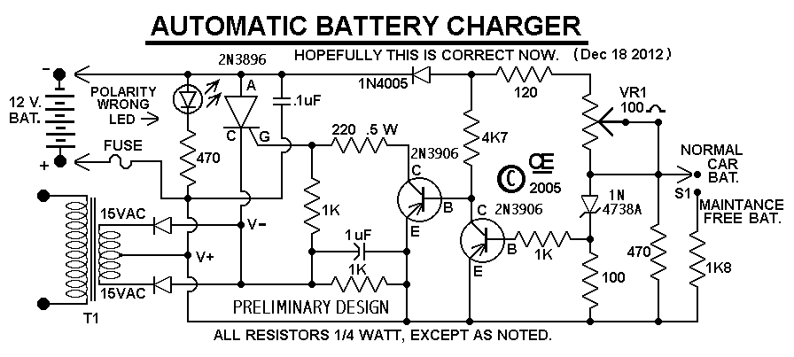
This is a schematic diagram of a full automatic 12v battery charger for charging the batteries of automobiles etc. Manualslib has more than 266 schumacher battery charger manuals. The charging current through the regulator, ic1 and the switched series resistors is 107 ma (47ω); The lead acid battery charger circuits explained in this article can be used for charging all types of lead acid batteries at a specified rate.
Pulsed charge pulsed chargers feed the charge current to the battery in pulses. You need to be very careful while building this circuit, as ac mains 220v is involved here. This is a circuit diagram example for mobile phone battery charging. Charging is accomplished with a constant current of 60 ma for aa cells to a this is the circuit diagram of rechargable battery charger which use solar cell / photovoltaic as the dc source.
18 741 просмотр 18 тыс. The circuit draws current from the +5v available a usb connection and pumps about 70ma of current into the battery. All these designs are thoroughly tested and. This circuit has a maximum 2 amperes.
This is a 5v adaptor not charger. Download 266 schumacher battery charger pdf manuals. This circuit will give adjustable dc supply output and charges battery ranges from 6 volt to 12 volt. The battery can be connected to the charger circuit by using crocodile clips.
In this unit, the full load current of the supply transformer/rectifier section was 4.4a. Draw circuit diagrams with online circuit diagram software. Here is the complete circuit diagram for cell phone charger circuit: Charger circuit is inbuilt in phone which gives 4.2v to battery and does cc+cv+trickle charging.
The incorect usage is please make the pcd layouts also large as the circuit diagram. This should be enough current to fully charge a pack. Next is the circuit scheme of automatic 12v battery charging or accui to simplify the assembly i provide a pcb layout diagram with 2 layers as shown below Meaning you can this charger for charging a 1ah battery or a 1000 ah battrey, just by upgrading the transistor.
Click on an alphabet below to see the full list of models starting with that letter I have removed the 2 circuit boards (pictures attached) and see no visible evidence of burning or overheating. In the charging section, regulator ic1 is biased to give about 7.35v. More batteries are damaged by bad charging techniques than all other causes combined.
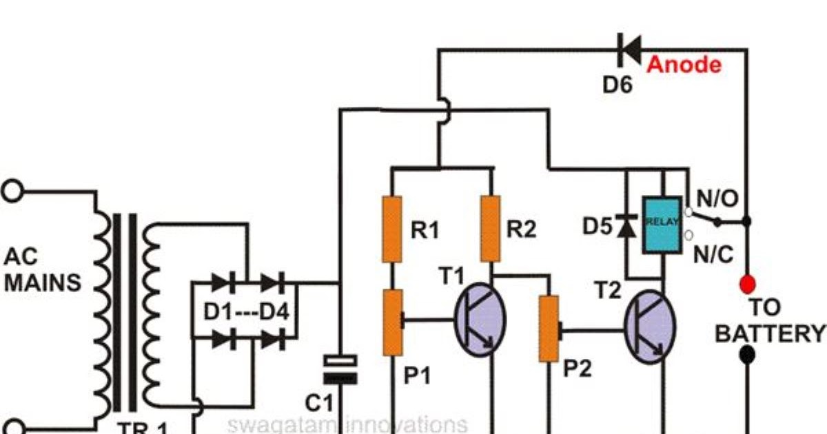
The charger consists of a mains transformer, tr1, bridge rectifier b1and smoothing capacitor c1. That way it is easy to take a print of the. .charge the battery.when the battery connected to the charger gets discharged the battery. As can be found the circuit is an automatic battery charger circuit, consisting of an operational amplifier that is responsible for governing the state of the battery to identify the actual.
Battery chargers and charging methods. Circuit boards not available any longer. This nicd battery charger can charge up to 7 nicd batteries connected in series. Mobile charger circuit diagram new solved wiring diagram for.
Schumacher battery charger wiring diagram. Schumacher se 5212a wiring diagram beautiful best 25 automatic. This solar battery charger circuit has auto cut off function so it will automatically stop charging when the battery become full charge. When the battery connecter to the charging circuit, the battery will not be dead completely and it will get discharged this will give the forward bias voltage to the transistor through the diode d2 and resistor r7 which will get.
Lithium battery charging with an alternator. The lm317 is a monolithic integrated ic comes with three different packages. Tying to charge a 6v car battery with this 12v charger.


