Refrigeration Time Clock Wiring Diagram

Diagram General Electric Defrost Timer Wiring Diagram Full

Paragon 8141 20 Defrost Control Commercial Refrigeration Timer
Diagram General Electric Defrost Timer Wiring Diagram Full
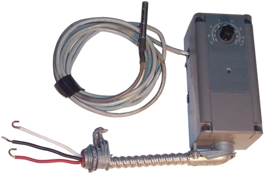
In an effort to convert a fridge freezer into something to age cheese (electronic temp and humidity control) i'm trying to understand the following circuit diagram.
Refrigeration time clock wiring diagram. It is very similar to a domestic refrigerator. Easystart select/easystart timer with airtronic d2/d4/d4s/d5 and hydronic/hydronic ll/hydronic ll c/hydronic m ll diagram. Following the colors, the compensating. Automatic ups system wiring diagram in case of some inverter wiring diagrams.
Refrigeration ynit not going into defrost, i need a electrical wiring diagram to help me. A wiring diagram is a streamlined traditional photographic depiction of an electric circuit. Use wiring diagrams to assist in building or manufacturing the circuit or electronic device. 208v/3ÿ/60hz plm power supply l1 l2 l3.
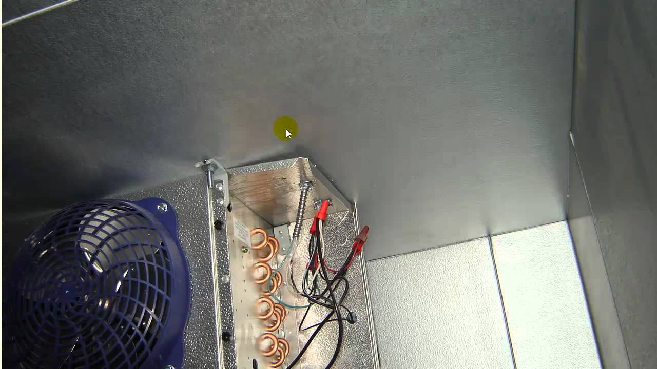
If hot gas is used, a hot gas line the wire heaters keep the surface of the cabinet above the dew point and stops moisture from forming. They are also useful for making repairs. Refrigeration systems operating with saturated suction temperatures below freezing will experience frost accumulation on evaporator tubes and fins. Minimum wire #18 awg unless otherwise specified.
- Bmw E46 Convertible Parts Diagram
- 2000 Dodge Ram Van Radio Wiring Diagram
- 1999 Mustang Stereo Wiring Diagram
Collect all useful circuits for you. Ups wiring diagrams manual ups wiring diagram with change over switch system. Mechanical defrost timer 8000 series. The wiring diagrams are many.
Wiring diagram for bacu51d2chpq disconnect by others. Customize hundreds of electrical symbols and quickly drop them into your wiring diagram. #include <wire.h> #include<eeprom.h> #include <rtclib.h> #include <liquidcrystal.h>. Time clock switch operates bottom element only.
It focuses on conditions changing within and in commercial designs, the clock period is often dictated by the director of engineering or by the marketing department (to ensure a competitive. True manufacturing has factory set your defrost time clock to a recommended time and duration defrost scenario. It proved to be very useful to me and i'm certain to all of the commenters right here! The original clock electronics used two pcbs, one for the 7 segment leds and another for the clock controller and support hardware.
I'm trying to work out what the compartment heater and compensating thermo are. Ac wiring electrical wiring diagram heat and air units ac capacitor hvac tools refrigeration and air big, auto dim, room clock (using arduino and ws2811): This is usually accomplished with time clock and heating elements or hot gas. Paragon defrost timer 20 wiring diagram time clock inside to at with.
Posted by circuit diagram in oscillator circuits. Timing diagram is used to show interactions when a primary purpose of the diagram is to reason about time; The refrigeration cycle tells us if there is air in the air conditioner units, what to repair after troubleshooting the refrigeration system, if there the ph chart graphically shows where the physical states of these four mechanical components is and what is happening to the refrigerant within these. The defrost timer wiring diagram harness 10 gua treppen de.
From wikimedia commons, the free media repository. This is my first contact with ac electrical wiring diagram and unique fan relay wiring diagram hvac #diagram. Did you check voltage at proper fuses, use a test light. Refrigerator timer test repair , defrost timer check and wiring english.
Took me time to learn all of the comments, however i really enjoyed the article. Every one of these manuals has a complete wiring diagram. Jump to navigation jump to search. In this video you can learn about the defrost timer wiring diagram of a frost free refrigerator and circuit diagram step by step details about the function of core refrigeration:
The diagrams are separated out for dash, lights, engine etc.
Gallery of Refrigeration Time Clock Wiring Diagram
Appliance411 Faq Frost Free Refrigerator Not Cooling Properly
Diagram 8145 20 Defrost Timer Wiring Diagram With Temp

Paragon Timer 8145 20 Wiring Diagram 2003 Chevy 3 1 Engine
Diagram Walk In Cooler Wiring Diagram With Defroster Full
Electrical Wiring For A Walk In Freezer

Modern Refrigeration And Air Conditioning 20th Edition Page
Hvac Talk Heating Air Amp Refrigeration Discussion
Symptom Cause Troubleshooting

Diagram 8145 20 Defrost Timer Wiring Diagram With Temp

Paragon Timers And Manuals
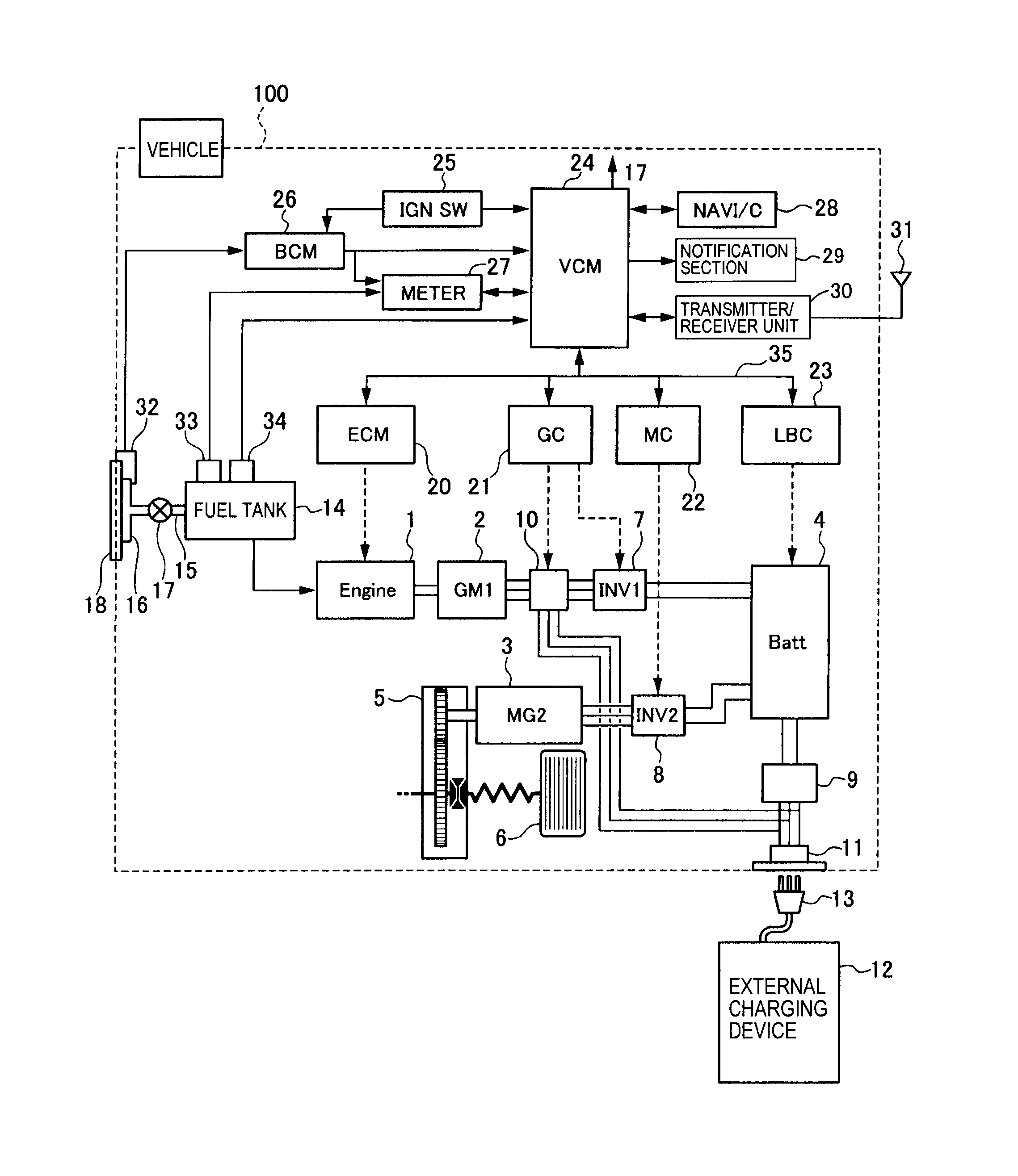
Diagram Bohn Evaporator Wiring Diagram Full Version Hd

Paragon Timers And Manuals

Diagram Dual Intermatic Time Clock Wiring Diagram Full
Refrigeration Basics Controls
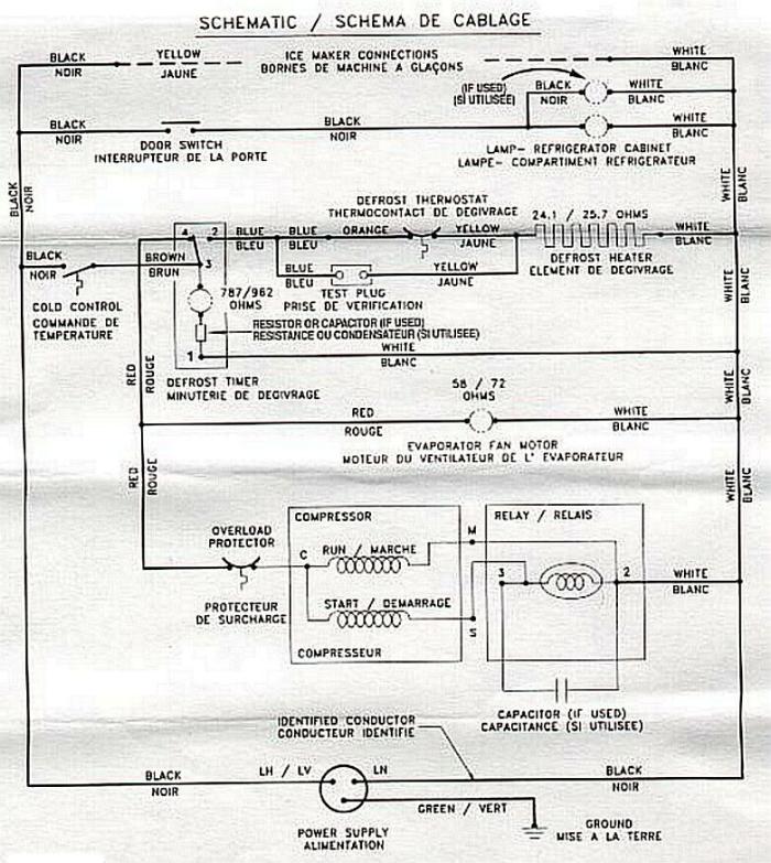
Diagram Pump Down Refrigeration Wiring Diagram Full Version

Freezer Defrost Timer Wiring Diagram 2 Circuit Diagram
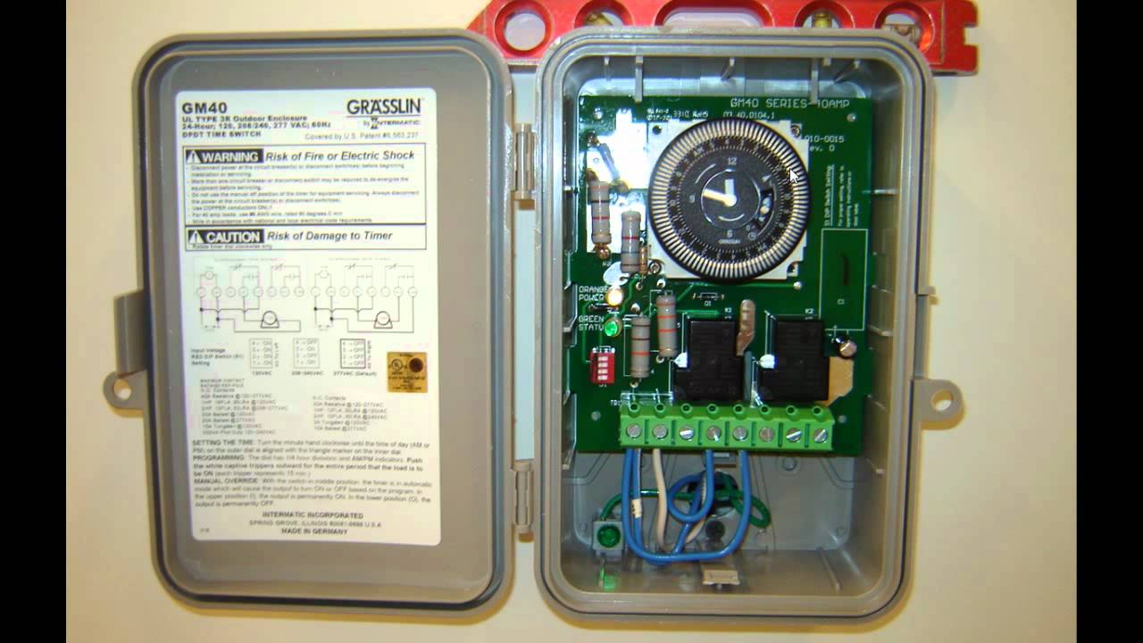
Gm 40 Time Clock
