Quicksilver Throttle Control Wiring Diagram
In etc systems, a vehicle's electronic control unit uses information electronic throttle control is a closed loop system.
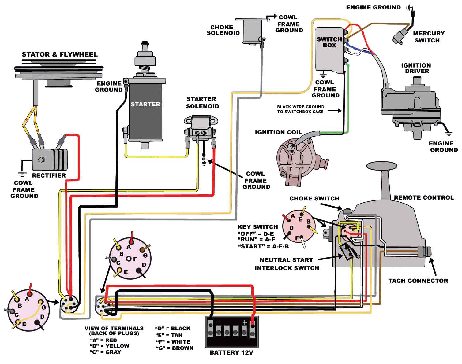
Quicksilver throttle control wiring diagram. The throttle controller is a quicksilver na1601 and all the plastic bushing have broken. I had issues at first because i made the assumption it was shipped on neutral. In this section, we'll focus on the electronic throttle body. Erratic operation from the throttle wiring getting wet is a known issue.
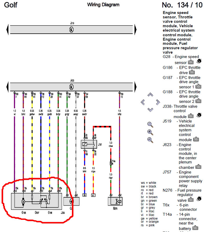
22.04.2020 · quicksilver mander 2000 wiring diagram car quicksliver throttle shifter wiring diagram and mercury quicksilver shift. When looking down at the electronic throttle body's connector, the. Electronic throttle control (etc) is the automobile industry's fly by wire system. (i) an accelerator pedal module (ideally with two or more independent sensors), (ii).
It is not difficult to learn the basic symbols. Works great as a replacement for quicksilver 3000 throttle wired colors all match up. The throttle opens based on user input (which is transmitted to the ecu via the accelerator pedal. You will be checking for continuity on the vq35de throttle control unit harness, so please refer to the throttle control unit harness wiring diagram above.
- Husqvarna Lawn Tractor Wiring Diagram
- 1998 Harley Davidson Softail Wiring Diagram
- Wahl Clipper Diagram
In this video i remove the quicksilver commander 4000 pistol throttle from my boat, disassemble it and identify some areas causing a significant amount of. Throttle actuator control (tac) module. This throttle control can often be called the throttle position sensor, tps, drive by wire, dbw or electronic throttle. Electronic throttle control (etc) is an automobile technology which electronically connects the accelerator pedal to the throttle, replacing a mechanical linkage.
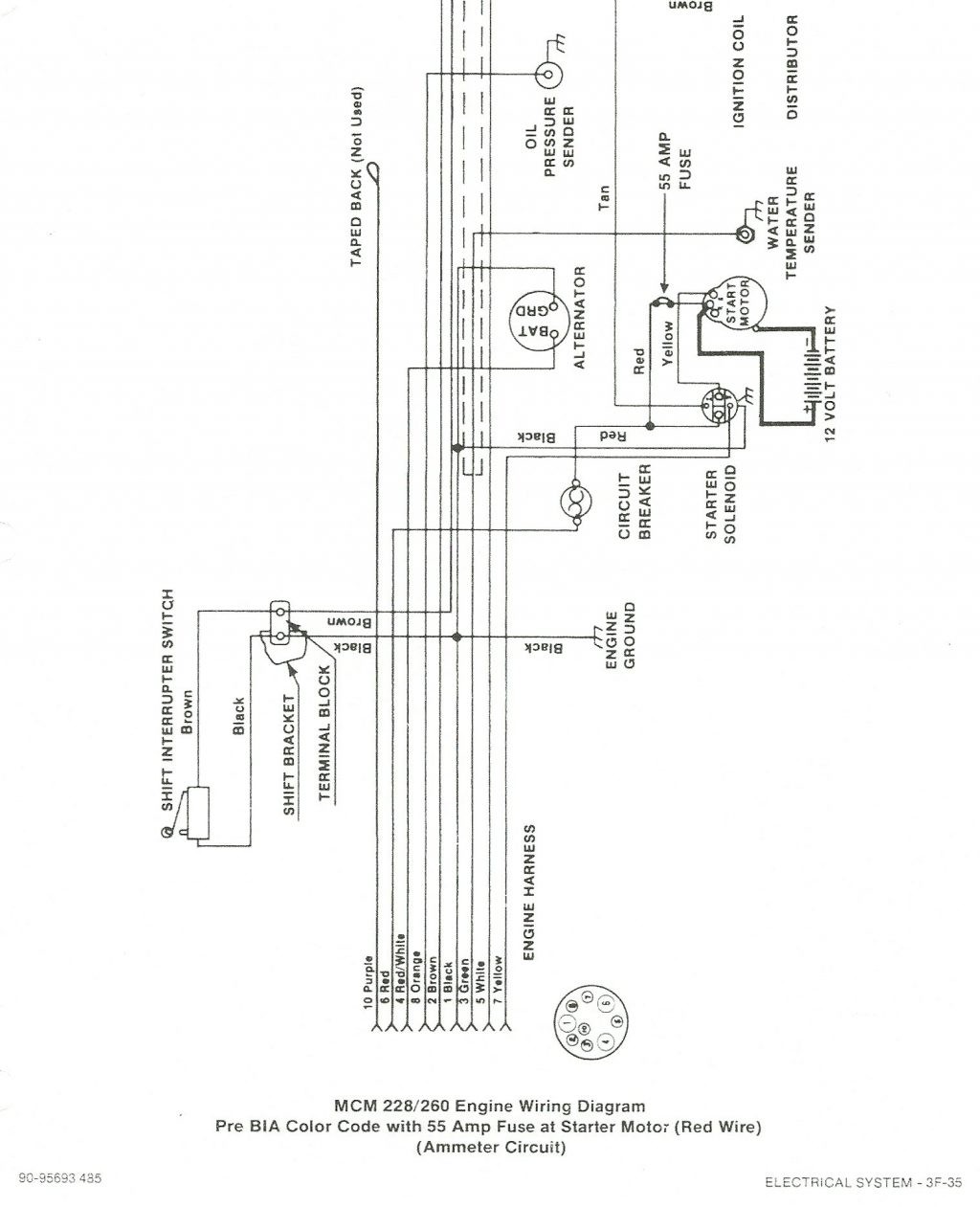
• hynautic control slave units • hynautic control tubing. These two sections help the technician pinpoint problems occurring in the electrical system. In wiring diagrams, the single circuit diagrams cover each sensor and subset of the electrical system of the engine. Use a voltmeter to determine which pins are 5 v reference, idle validation, and engine control signal.
The infinitypro cable needs to be wired to the cab foot throttle harness. On the examples below or any other diagram, be throttles on both sides will offer much better control. Use of parts other than recommended service replacement parts. February 11, 2019february 10, 2019.
Here's a brief description of the throttle position sensor (tps). After all, if a mechanical throttle control system works, why make it more complicated? Mercury throttle control removal, mercury throttle diagram, mercury smartcraft throttle manual, mercury throttle control handle. Ecm and pcm abbreviations note:throughout this manual the computer diagnostic.
Wiring diagrams show the connections to the controller, while line diagrams show circuits of the operation of the controller. This is the model with the gear shift combined with the throttle. As you have probably already observed, there are 8 wires sticking out of the electronic throttle body. Once you do, you are able to read diagrams quickly, and can often understand a circuit at a glance.
Refer to the engine specific wiring diagram for infinitypro interface connections. Refer to gauge manufacturer's instructions for specific connections. If the driver opens up the throttle the injected fuel must be enriched during 9.4.3. A typical etc system consists of three major components:
It does not matter if the tps signal is rising or falling when. I'm looking for a wiring diagram for a mercury 75 hp 4 stroke s/n:0g982237 production year 2007 thank you. A throttle (or cab) is a method to control the locomotives and other aspects of the layout (turnouts, animation, lighted passenger cars, etc). Electronic throttle control systems may seem a little silly.
This remote control features a finger tip neutral lock release, throttle only option, power trim switch, and a lanyard stop switch. Quicksilver throttle assembly tilt and trim button will not work on the up position, down works great of course make sure all cables and other wires are clean. The throttle position sensor must be wired up according to the diagram below. There are many types of throttles available, with some features overlapping various types.


