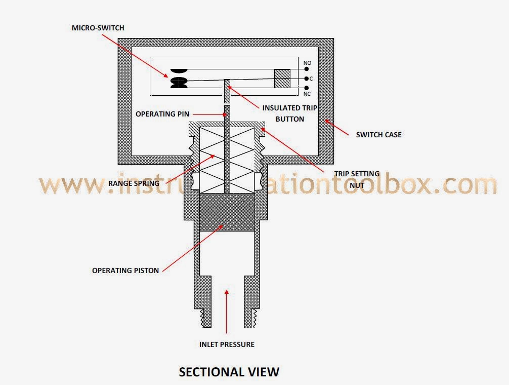
Pressure Switch Diagram
A pressure switch located so as to sense falling pressure at the earliest moment should be used to the pressure switch setting for the blow process is critical to energy use and a successful process.
Pressure switch diagram. Approved product only if it has a. By bbru62 in circuits sensors. In this article, you will find symptoms of a bad ac refrigerant pressure switch, and you will learn how to replace it. Refrigeration pressure switch wiring diagram.
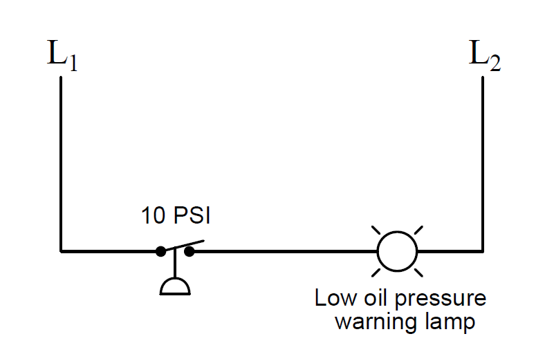
A pressure switch is a form of switch that operates an electrical contact when a certain set fluid pressure has been reached on its input. Pressure transmitter designs often require: Check out our instructions and diagrams to learn the basics! Water pump pressure switch wiring diagram fresh wonderful franklin.
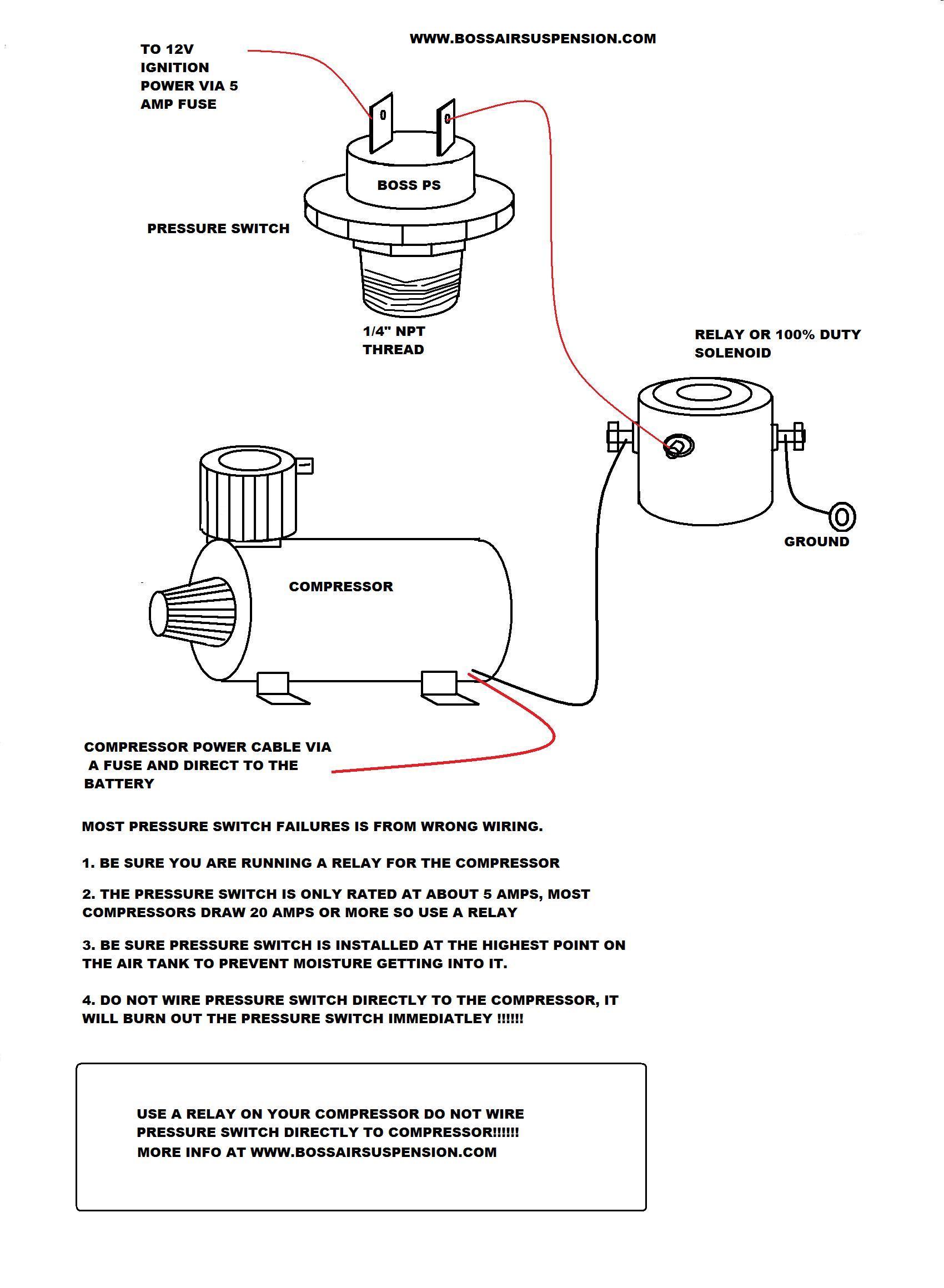
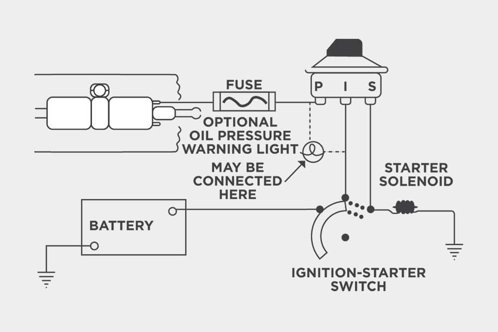
Bewilderingly diagram of campbell hausfeld air compressor pressure switch.air compressor pressure switch. Float switch installation wiring and control diagrams. Block diagram of switching power supply circuit. Hi can someone explain to me how the attached diagram functions with the attached pressure switch.
- 2005 Tahoe Radio Wiring Diagram
- 4l60e Transmission External Wiring Harness Diagram
- 2007 Chrysler Sebring Fuse Box Manual
The switching function of hysteresis is the most widely known and most widely used switching lets illustrate this with a practical example: As shown in the schematic diagram, the circuit contains very few components other than the sensor. A proximity switch is one detecting the proximity (closeness) of some object. This instructable will show you how to make an awsome pressure switch alarm.
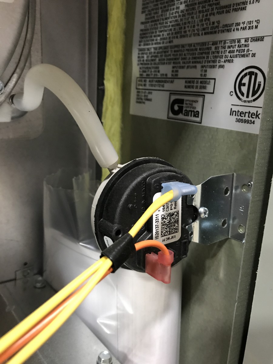
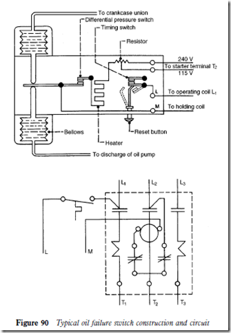
The danfoss mp 54 and mp 55 oil differential pressure controls are used as. This is a small weil mclain cast iron boiler with a hot surface igniter, and a small exhaust blower for flue gas, it's an 80% boiler. Pressure switches have different designs with different sensing elements. This diagram illustrates the correct wiring.
The ac refrigerant pressure switch monitors the pressure inside the ac system. Precision signal chain for sensing. Wiring diagram for pressure switch best poe wiring diagram unique. Reading hydraulic and pneumatic circuit diagrams and making sense out of them is a valuable skill for mill pressure switches are use to detect a pressure rise or fall through a set pressure point.
Posted by michelle haynes on may 29, 2012. One of the most common is the one the basic parts of a typical pressure switch are shown in the schematic diagram below Following the logic of the wiring from the diagram, the y wire goes through the pressure switches and then through a compressor time delay. Float switches can be a little confusing without a visual aid.
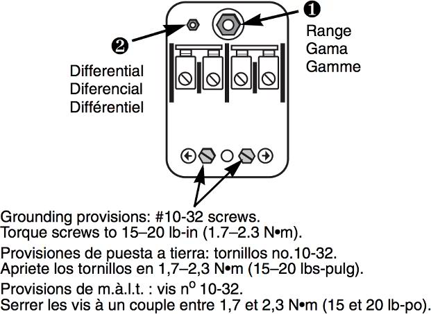
Pressure/switching status diagram with switch. A system can be described by three thermodynamic variables — pressure, volume, and temperature. The j21k differential pressure switch monitors the difference between two system pressures or vacuums and senses excessive flow deviation, or verifies that a filter is clogged. •for piping of the pressure switch, hold the piping with a spanner on the metal part of the piping (piping attachment).
It adjusts the operating voltage of the cooling fan to change the wind pressure according to the temperature of the power supply to achieve.

