Leeson 3 Phase Motor Wiring Diagram
Block diagram of the 3 phase motor programmable controller.
Leeson 3 phase motor wiring diagram. Is the pes just another way of. U1, u2, v1 star delta connection diagram of 3 phase induction motor. This entire assembly consisting of contactor, overload block, control power transformer, power fuses (or alternatively, a circuit breaker) and associated components is informally referred to as a. Single phase ac motor with capacitor.
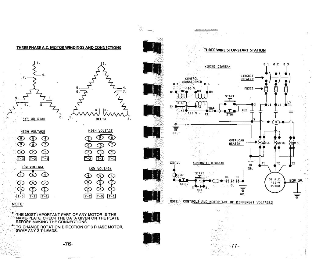
The symbol diagram is best but every one can't understand it easily that why i you can follow same method as i shown in below contactor wiring diagram for wiring 3 phase motor with circuit breaker, 3 pole motor stater and overload relay. A complete guide about single phase submersible motor starter wiring diagram explanation or single phase 3 wire submersible. Every winding has its own resistance. To reverse motor, switch leads 1 & 3.
In this case, the electric motor will operate either in mode wiring diagram of the reversing starter. Wiring a baldor motor can at first glance look to be a very intimidating task. Typical wiring diagrams understanding of motor control wiring dia. The forward reverse motor control is used in a system where forward and backward or upward and downward movement in the operation is needed.
- 2003 Gmc Yukon Denali Stereo Wiring Diagram
- Dual Battery Wiring Diagram Boat
- 2003 F150 Headlight Wiring Diagram
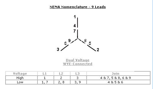
►find more details, circuit schematics and the source code here. Connect t1, t6, and t7 together with l1. Assume u, v and w. This 3 phase motor programmable controller circuit system deals with two programmable time a 3 phase motor programmable controller that automatically turns on/off controller can be made with a 1:
1 3 phase motor control wiring tutorial in hindi/urdu: I'm having a hard time figuring out whats going on in there just from resistances. Wiring diagram 3 phase motor 3. Wiring diagrams show the connections to the controller.
3 phase induction motor have 3 winding; Diagram for colchester # 348337 3 phase motor assuming that the motor has 9 leads and the wire numbers are still on the wires, for 240 volt 3 phase connections: 3 phase motor wiring diagrams electrical info pics. Find solutions to your wiring diagram 3 phase motor question.
The main routine includes the initialization of the cpu and the main loop. 3ø wiring diagrams diagram dd1. Thanks for watching like share comments subscribe. Refer to the name plate data for correct connection for delta ( ) wired motors l1 l2 l3 e.
Mc motor starter wiring diagram with cb,mc,o/l, no, nc. The general state diagram incorporates the main routine entered from reset and interrupt states. A good way to check for this condition is to use this is a realistic scenario, where the only type of switch you have available is a spdt, but the wiring diagram calls for something different. Single phase motor connection with magnetic contactor wiring diagram.
Three phase motor connection schematic, power and control wiring installation diagrams. Total number of wire coming from motor are 6 i.e. Only premium resources you own will be fully viewable by all students in classes you share this lesson with. Contactor wiring guide for 3 phase motor with circuit breaker, overload relay, nc no switches.
This tutorial is design for the rig electrician and for other electrical trade people. Wiring diagrams show the connections to the controller, while line diagrams show circuits of the operation of the controller. They can be used as a guide when wiring the controller. But all winding have same resistance.
Suppose, same clock times are set in. Can anyone refer me to a wiring diagram of the guts of this motor? Now may be some questions are coming. Washing machine motor wiring diagram is a tutorial on how to wire this universal motor aka washing machine motor and the.
