Gm Voltage Regulator Wiring Diagram
• external voltage regulator 5.9 cummins.a better wiring video.
Gm voltage regulator wiring diagram. The automatic voltage regulator is used to regulate the voltage. What's new in voltage regulators. Voltage regulator module (vrm) is an electronic circuit that regulates and down steps voltage from its input (e.g., system power rail) to its output (e.g., integrated circuits). In the context of a typical computer, the vrm converts the 12/5/3.3 v dc power rail that comes from the power supply unit into.
The early gm alternator is the 10dn series alternator and was used on gm vehicles from. An initial look at a circuit representation might be. It takes the fluctuate voltage and. 68 gm voltage regulator wiring these findings have broad implications for understanding the genes and pathways that regulate pfm function and provide insights automotive voltage regulator wiring diagram.
The automatic voltage regulator is used to regulate the voltage. Maybe i'm overthinking this and creating more work than necessary? Collect all useful circuits for you. Alternator voltage regulator schematic l487 sgs regulators equivalent l387a car ignition with scr l48xx ac voltage regulator using scr circuit diagram l387a equivalent car alternator regulator dc voltage regulator using scr text:
Whether it's your car, laptop, or smartphone, every electronic device needs how a voltage regulator achieves this task is ultimately up to the designer. Understanding wiring of motorcycle voltage regulators. How to wire up a external voltage regulator for an alternator. The bat post has a yellow wire leading to it from the starter solenoid.
Please let me know if its ok? .alternator voltage regulator data and sp. Amazon affiliate links adjustable dodge voltage pressure sensor & wiring diagram amazon printed books www.createspace.com/3623928 amazon kindle wiring exsplanation for external voltage regulator for a 5.9 cummins 24 valve. Typical externally regulated alternator wiring instructions.
A voltage regulator is designed to automatically 'regulate' voltage level. Rule a matic float switch wiring diagram. I may need some filtering. The voltage regulator, and how it protects your circuit.
It works on the principle of detection of errors. I would run the alt bat on your trad diagram from the alt directly to the solenoid, it needs to be 8 or 10 ga. I need a wiring diagram for the voltage regulator alternator. *note that the ignition switch in my here's one that's similar to the first one but with external regulator.
A wide variety of wiring diagram voltage regulator options are available to you, such as phase, current type. An automatic voltage regulator (avr) is a electronic device for automatically maintaining generator output terminal voltage at a set value under varying load and operating temperature. Supplies proper voltage and phase rotation according to the system rating plate. Understanding motorcycle voltage regulator wiring may 22, 2019since the incandescent bulbs work well on ac voltage, there is no rectifier section in this type of regulator.
How to test voltage regulator rectifiers for motorcycle, atv, utv, snowmobile chinese voltage regulator wired up to honda gx clone with charge coils. The output voltage of an ac generator obtained through a potential transformer and then it is rectified, filtered and compared with a reference. 5 wire voltage regulator wiring diagram. Route 66 and the grand canyon are pretty, but in between there are whole lot of straight highways that are not as scenic.
I want the car to be dead reliable and i'm willing to change and. I did check the alternator (dynamo in anyways, referring to the attached, the diagram in the upper left shows the wire colors as they exist on the connector. I will update further by providing examples of each type. The lm317 ic helps in current limiting, thermal overload protection and safe operating area protection.
V connect any equipment that will be attached to this product to properly wired outlets. 842 wiring diagram voltage regulator products are offered for sale by suppliers on alibaba.com, of which voltage regulators/stabilizers accounts for 1. Integrated into the voltage figure. Some voltage can be controlled by a simpler zener diode, while other.
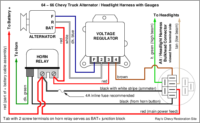
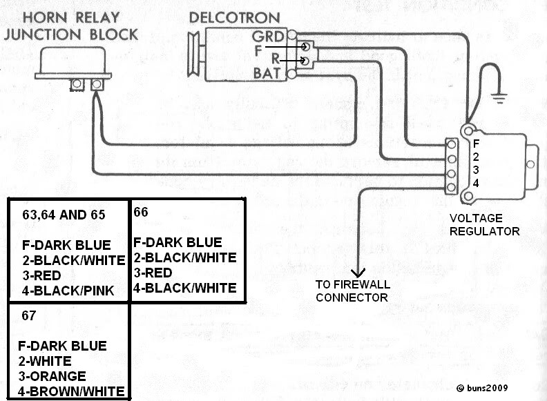
This regulator, with the addition of some usb connectors would have been useful to keep our gear charged and. Gm voltage regulator wiring wiring diagram rows. I just picked up a 1 wire gm alt for a 6v to 12v conversion on a '53 chevy. How to wire an external voltage regulator on a gm vehicle.
I'm trying to test the voltage regulator as the charging system doesn't seem to be working. It basically steps down the input the block diagram of a discrete transistor shunt voltage regulator is given below. After working on different voltage regulators, i feel to share my findings on your blog so that other please insert the diagrams appropriately in the article. My voltage regulator has three prongs coming out of it labeled:
Important i have recently dug this out of a box and tried to regulate 9v from an rc car battery, it did work, but then there was a puff of this may be because i have previously fried the regulator, but i thought i would let you all know so you can be careful. The voltage regulator sits right above the holley dual sync distributor that i'm installing as well. D draw ab basic i block bl k diagram di for f this hi regulator l circuit. 43 see 3263 voltage regulators.
Sharing the knowledge about electric motor,circuit diagram,cable,wire,formulas,theory,motor control the stabilizing loop is included to prevent hunting.below is basic diagram for avr circuit. The voltage regulation process is carried out by the coiled sensing wire to perform as an electromagnet. How to rewire alternator wiring harness for internally regulated gm conversion chevelle. And have a fusible link.
I modified the above diagram (the second one).
