End Of Line Resistor Wiring Diagram
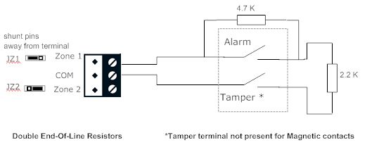
Here is shown an alarm zone circuit with terminating resistor and a mixture of normally closed and normally open sensors and the circuitry inside the alarm.
End of line resistor wiring diagram. What is their purpose and how do you use them? Fixed resistors are used in electronics. A resistor will be represented with a series of squiggles symbolizing the restriction of current flow. The diagram below shows a typical sensiscan 2000 installation and is provided as a guide for proper wiring placement.
Resistor d which of the following describes a drawing or chart of an electrical circuit using lines and symbols to. End of the line, or eol. So what our resistor's going to do is actually supervise the wiring. For a complete description of how fire zones.
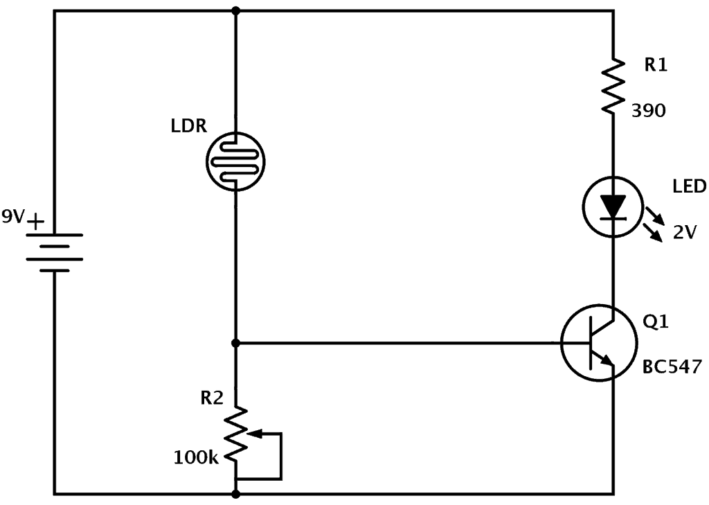
This simple ldr circuit diagram shows how you can use the light dependent resistor to make an led turn on and off depending on the light. Then the point between the fixed pulldown resistor and the variable fsr resistor is connected to the analog input of a microcontroller such as an arduino (shown). A resistor is used to restrict the amount of current flow through a device. Please refer to figure 1:
- 1987 Ford F250 Starter Solenoid Wiring Diagram
- 2008 Honda Accord Serpentine Belt Diagram
- Craftsman Yt3000 Transmission Belt
The purpose of eolr's is to allow the control panel to supervise the field wiring for open or short circuit conditions. Connection diagram and familiarise yourself. Tamper (short and open) conditions as must be wired according to the following diagram: Here is the schematic for the circuit
How to wire up a pir using end of line /eol resistors. Jumper wires with alligator style spring clips at each end provide a safe and convenient method of electrically joining components together. When overall connections are required, see the overall electrical wiring diagram at the end of this manual. We hope to answer all of your questions in our video below!
This is used to isolate between the live and neutral connections in the main electrical line. And we're curious about the voltage across one of them. 3 035 просмотров 3 тыс. In electronic circuits, resistors are used to reduce current flow, adjust signal levels, to divide voltages, bias active elements, and terminate transmission lines, among other uses.
Reference the systems installation wiring diagram (iwd) for specific connection and component information. Everywhere else, it should be at. Above the beetles is a resistor labeled brown blue orange. Car stereo wiring diagram image from end of line resistor wiring diagram , source:galericanna.com pioneer dxt x2769ui wiring diagram best end what's eol end of line resistor ?
It's important to understand that the signals used in fire alarm systems are dc, either on or off, not ac. Electronics tutorial about resistors in ac circuits and the impedance of a resistor in an ac circuit due to the frequency of a sinusoidal waveform. Regen resistor sizing and configuration. Provides circuit diagrams showing the circuit connections.
Note that our method takes the somewhat linear resistivity but does not provide linear voltage! So, we basically just have a pattern here with the series resistor, driven by some voltage from the ends of the two resistors. 1 load i2 = shaft speed at the end of deceleration in radians per second. But electrically still at the end of the line.
Wiring diagrams show the interconnection of the multicore cables, for example, between the switchgear and the associated control panels, and the these diagrams are required to facilitate the wiring of the measurement, protection and control equipment at the substation construction stage. A wiring line diagram is to represent the wiring of your installation. So you would be able to tell, for instance, if you have a short in your wiring. Double end of line resistors allow the panel to determine if the.
Disconnect any and all auxiliary alarm devices. Back to the left end of the diagram, where the blender is, there is a wire that is labeled as a distance 3 8 from the wire with the 50v battery. The resistors are in series but we must make the assumption that that middle wire is for testing purposes only. They are a critical piece in just about the terminals of the resistor are each of the lines extending from the squiggle (or rectangle).
For rotary motor applications, gather this additional information: Also the schematic symbol used for defining an ac voltage source is that of a wavy line as opposed to a battery symbol for dc and this is shown below. It can also include actual manufacturers part details and in. Off the shelf security consoles utilize an end of line resistor to monitor the integrity of the cable runs, usually a 2 kohm resistor.
It is a simple but complete feature which includes all important components in creating drawings like the interconnections (cables) between locations, terminal strips and devices. Unlike a pictorial diagram, a wiring diagram uses abstract or simplified shapes and lines to show components. End of line resistors (eols) are very important for circuit and loop supervision. An antenna is a straight line with three small lines branching off at its end, much like a.
This provides what is typically call. Maretron sim100 user manual • switch without end of line resistor, revision 1.0 page 5 • maretron computer accessories. Most types of resistors are linear devices that produce a voltage drop across themselves when a current flows through them there are two basic fixed resistors are resistors with a specific value. An ldr or light dependent resistor is a resistor where the resistance decreases with the strength of the light.
Resistor an electrical component with a fixed resistance, placed in a circuit to reduce voltage to a.
