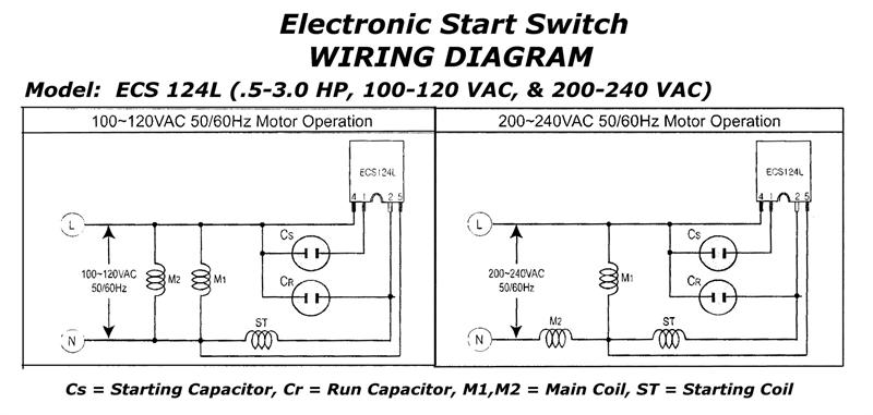
Dayton Single Phase Motor Wiring Diagram
Single phase terminal markings identified by color:
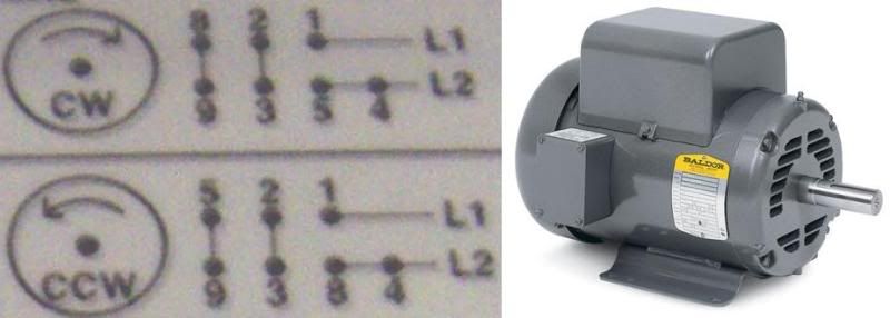
Dayton single phase motor wiring diagram. The wiring diagram is typically on the reverse of the cover plate. Applications of single phase induction motors the windings are wound in a way that current in both windings flow in the same direction, and we can see the same represented in the diagram. Narrow your search by selecting motor type, gearbox, voltage, and phase options for your desired motor. How to wire a 1 hp single phase 120 volt baldor motor when i wire up a 1hp sigle phase baldor i conect the 135 and 248 together the motor runs but starts getting hot and smoking after a while… read more.
You don't need a wiring diagram for 3ph. The post discusses a single phase variable frequency drive circuit or a vfd circuit for controlling ac motors and other similar inductive loads specifically do not like operating with frequencies that you will have to integrate the outputs from the ic 4017 from the above diagram to the hin and lin inputs. When one phase of a secondary opens page 13 figure 1.13: This wiring connection is also easy as 3 phase motor wiring.
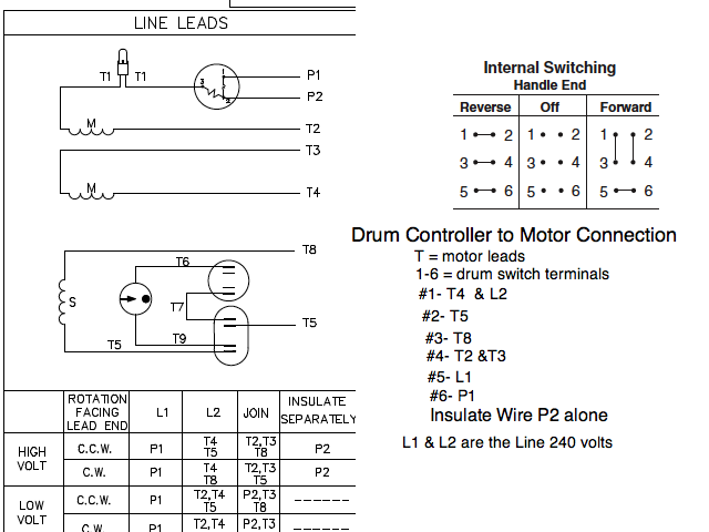
So before you start to wire your motor, you need to be sure what type it is. How to use the motor search tool. Wires are p1 purple p2 brown t2 white t3 orange t4 yellow t5 black t8 red. Given to you by an.
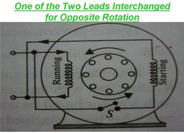
Below are wiring diagrams for four different types of single phase induction motor. These tips can be used on most. There should be a motor wiring diagram on the junction box cover. I dont see those capacitors anywhere, prehaps misboxed?
I'm in a pickle as the weather is turning here in ks and need to get this thing working asap. You just need to fing out what power you will power it with and read the inside cover for the wiring box on the motor. Old ge single phase motor wiring diagram. The 11 wires suggests its a 3 phase motor, based on a variety of dual voltage wiring info on the 'net.
The add states capacitor start/capacitor run single phase electric motor. In this video, jamie shows you how to read a wiring diagram and the basics of hooking up an electric air compressor motor. Dayton electric motor wiring diagram [pdf], dayton electric mfg. The reason behind this is very interesting.
Shaded pole motor wiring diagram. It is vital for dominant the e wiring. For this post i designed a diagram concerning distribution wiring, we will know as this breaker or dominant fuse box. However the link below mentions a 1.5 hp motor running on 110/220 (certainly single phase).
We need to know that. If we left a capacitor in the auxiliary winding after. The single phase motor are those motor which is working one phase and neutral (ground) supply for doing his duty and a 3 phase motor required 3 phase power i also published 3 phase motor wiring diagram which wired with contactor. Single phase wiring diagram for home.
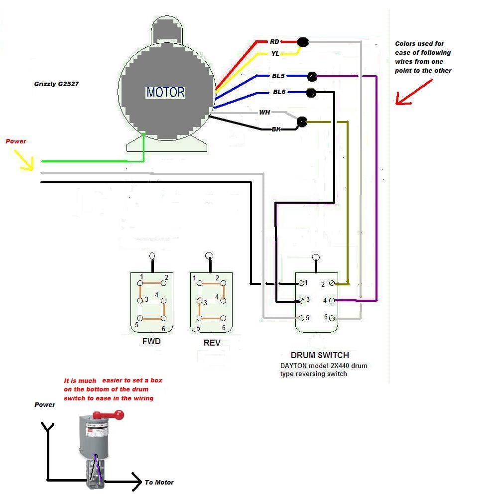
A single phase induction motor is an electric motor that operates on a single waveform of alternating current. I need a wiring diagram for a hobart reversible disposer with a drum switch. Electronic starter for single phase motor is used for protecting motor from over currents and different starter methods protection scheme of single phase induction motor. Within the diagram is shown the tactic of wiring distribution mainboard type utility pole to energy meter and so.
Start & run & dual capacitor specification references. That is not a single phase motor, that is a three phase motor. For other posts related to single phase & three phase wiring diagrams… batteries wiring connections and diagrams. This motor is single phase.
Notice incorrect direction of rotation. 1 phase & 3 phase wiring. Wiring diagrams, sometimes called main or construction diagrams, show the actual connection points for the wires to the components and terminals of the controller. Motors without brushes and commutators such as ac (alternating current) induction motors last the longest because of few moving parts.
Most electric motors, whether ac or dc, fail after time for reasons that may not be electrical in nature. Wiring diagram (ideally color) for dayton belt drive motor model. The stator poles are equipped with an additional winding in each corner called a shade winding as shown. A wide variety of single phase motor wiring diagrams options are available to you, such as applicable industries, certification, and warranty.
Howard st., niles il 60714 usa, retrieved 2017/07/09, original source: Power & control wiring trending.

