Allen Bradley Guardmaster Safety Relay Wiring Diagram
Allen bradley guardmaster safety relay wiring diagram.
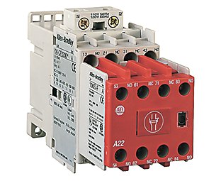
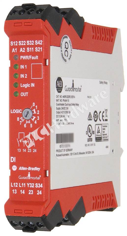
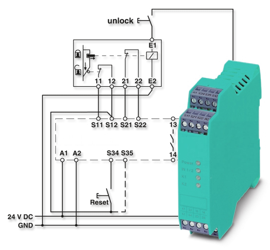
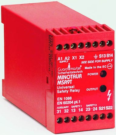
Allen bradley guardmaster safety relay wiring diagram. Guardmaster, msr5t, monitoring safety relays, automatic/manual, 24 v ac/dc производитель: Their main purpose is to allen bradley safety relays have been an industry standard for decades. This is a control engineering 2012 engineers' choice award winner. Chapter internal circuit block diagrams the figures in this chapter show the internal circuit block diagrams of each safety relay.
Guardmaster cannot accept responsibility for a failure of this installed in its free connector. We have a number of these allen bradley guardmaster safety relays in the plant. One normally closed, two normally closed, or. Safety relays • ethernet/ip enabled safety relays • configurable safety relays • modular safety current solutions § increase system cost and wiring by having each safety device connect.
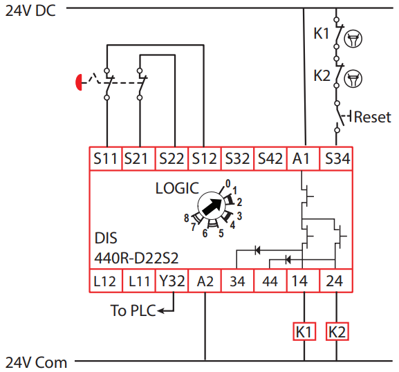
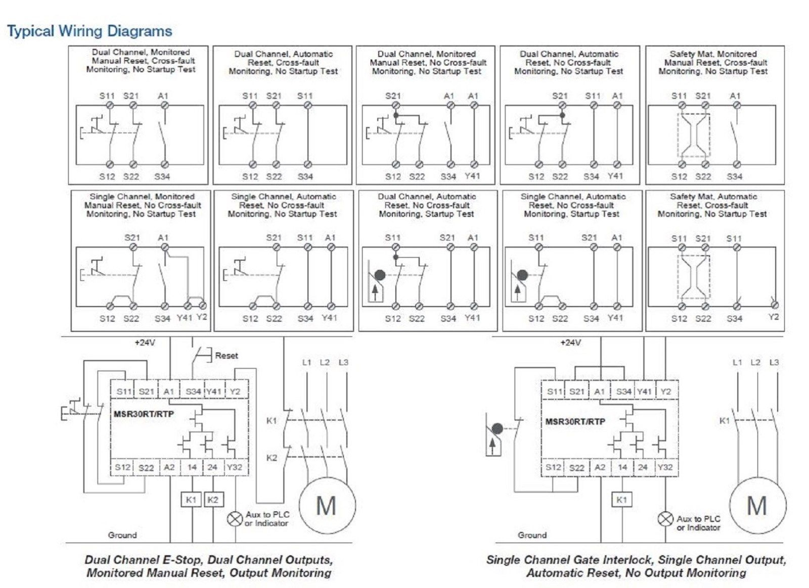
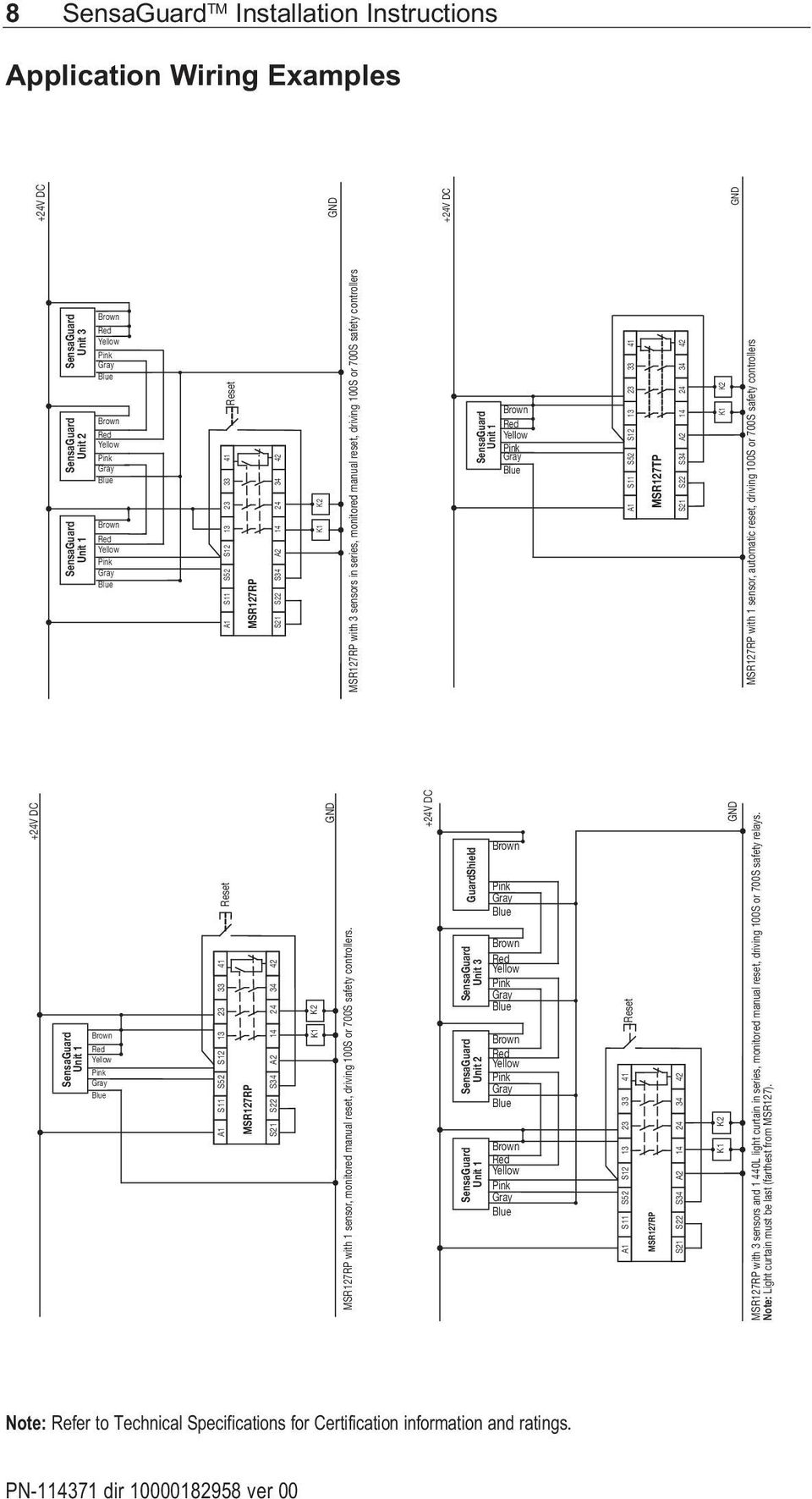
Safety applications and wiring diagrams. One normally closed, two normally closed, or with two pnp connections from a light description: Grounding the configurable safety relay. The status of each output relay of the expansion module is indicated by.
- 2011 F350 Fuse Box Diagram
- 2006 Ford Fusion Serpentine Belt Diagram
- Bosch Mass Air Flow Sensor Wiring Diagram
The msr127rt is a single function safety relay that can be connected in three different input wiring configurations: Guardmaster minotaur) is used for fault detection it is important to note the following: Next generation gsr safety monitoring relays. Safety circuits play an important role in industrial automation.
Ferrogard™ 1, 2, 20 & 21. Guardmaster relays pdf manual download. Safety is a critical issue in machine design. Safety relays are a special type of relay you can use to build a safety circuit.
5+ 12 v relay wiring diagram | cable diagram. When a monitoring safety relay (e.g. Safety relays use single wire safety (sws) signals that allow multiple safety relays to work in coordination with one guardmaster (and similar) safety mats can be connected to safety relays. All safety critical single faults, except for certain faults over the contact sets at the.
The guardmaster® msr127rtp can be connected in three different input wiring configurations: Figure 16 shows an example wiring diagram with sws input from a di safety relay and sws output. The manual has some block diagrams of the internal workings, but it depends on how they're wired as they can be configured to work in a few different ways depending on how you connect the wiring. The ability to interconnect guardshield pairs reduces overall system wiring and simplifies the safety circuit resulting in a lower overall cost of a multiple safety.
Safeguarding applications and wiring diagrams. Introduction to allen bradley guardmaster safety relays.

