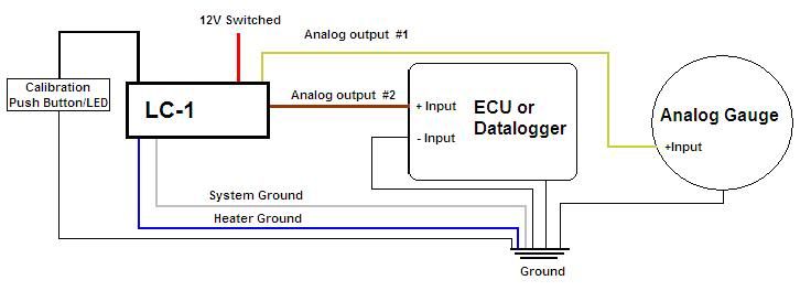
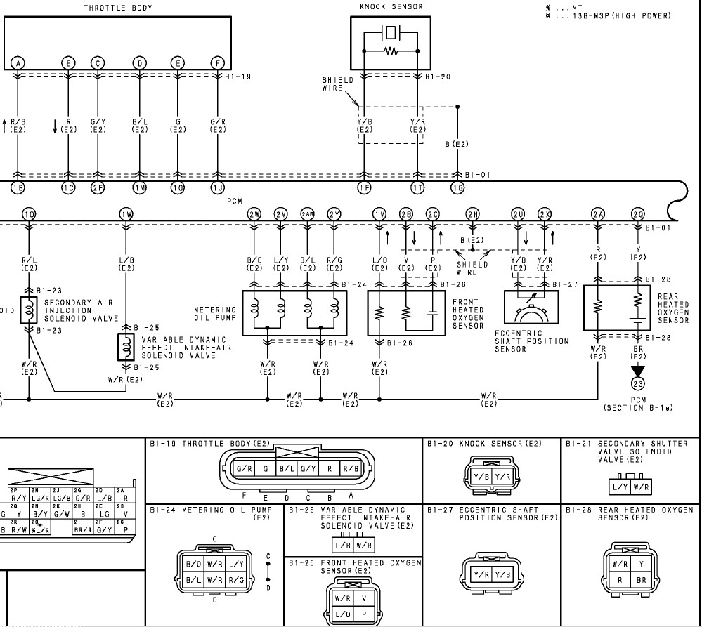
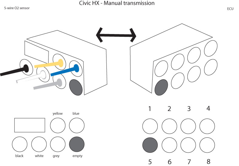
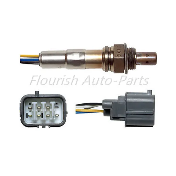
5 Wire Oxygen Sensor Wiring Diagram
In 20days after get your payment.
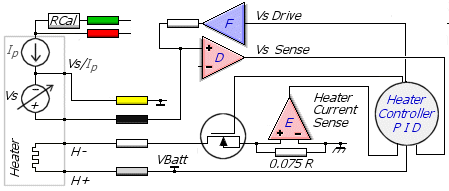
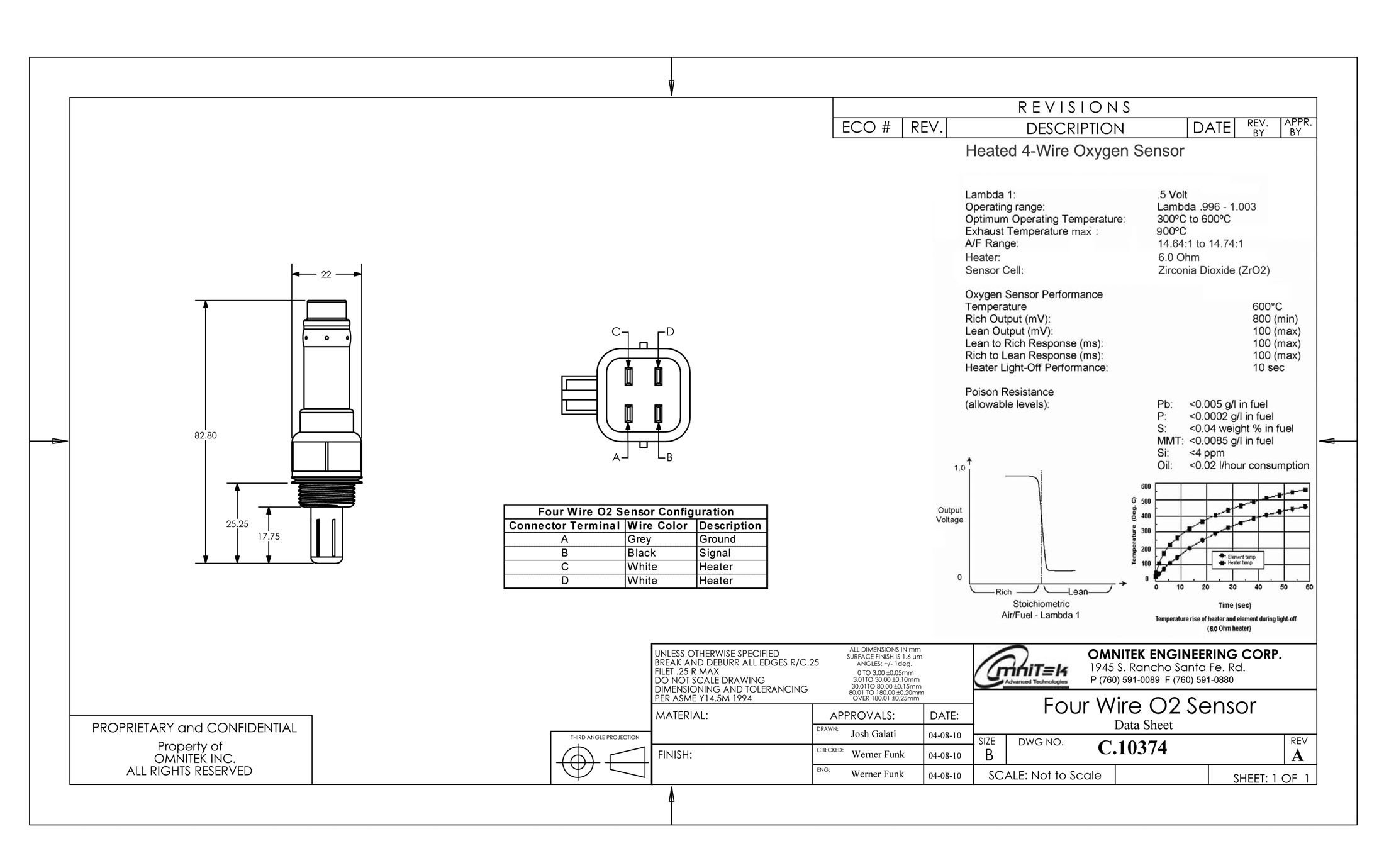
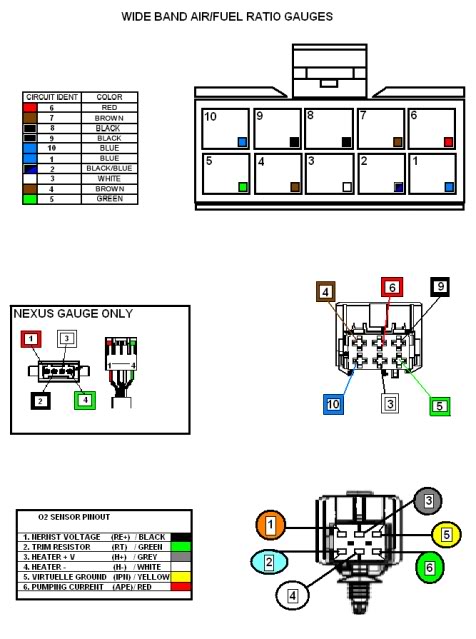
5 wire oxygen sensor wiring diagram. One oxygen sensor packed in a box. Does anyone have the wiring diagram for an oxygen sensor 4 wire? When replacing an o2 sensor, make sure it is the same type as the original (heated or unheated). Wide band oxygen sensors may also be referred to as 5 wire oxygen sensor, lambda sensors, lean burn oxygen sensors diagrams wiring free.
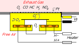
A heated oxygen sensor with two wires is usually wired like this (pic o2_sensor_diagram_2.jpg) one wire is 12 volts for the heating element. This technology allows for much faster warm up of the sensor because there is a much lower mass to heat and the heater is in direct contact with the sensing portion. A second oxygen sensor is now used downstream of the catalytic converter to monitor converter operating efficiency. It is very important that the sensor heater is not turned on, either manually or accidently.
How to use this manual this manual provides information on the h 1 headlight hi lh h 2 headlight hi rh h 3 headlight lo lh h 4 headlight lo rh h 5 heated oxygen sensor (main) h 8 horn lh h 9 horn rh. This may be a 0 to 1 volt signal directly from a. Are not labeled at the sensors themselves, as there are many possible sensors. My manual talks about using a test light between terminals a and.
On v6 or v8 engines with dual. The relay board takes 12v from the vehicle and passes it to the megasquirt® efi. Or does multiple oxygen sensor malfunction sound more like a ground wire. These sensors have an electrical resistance heater built in to them and will come to operating temperature usually within 1 minute.
In our next installment we will cover testing of exhaust oxygen sensors, pressure sensors, airflow sensors, and speed sensors. In many cases, by looking at the wiring diagram, developing an understanding of how the circuit works, and doing a few simple tests, you will determine the source of the fault. Rf oxygen sensor (o2s11) wiring diagram. The oxygen sensor signal is input in ecu since then more than.
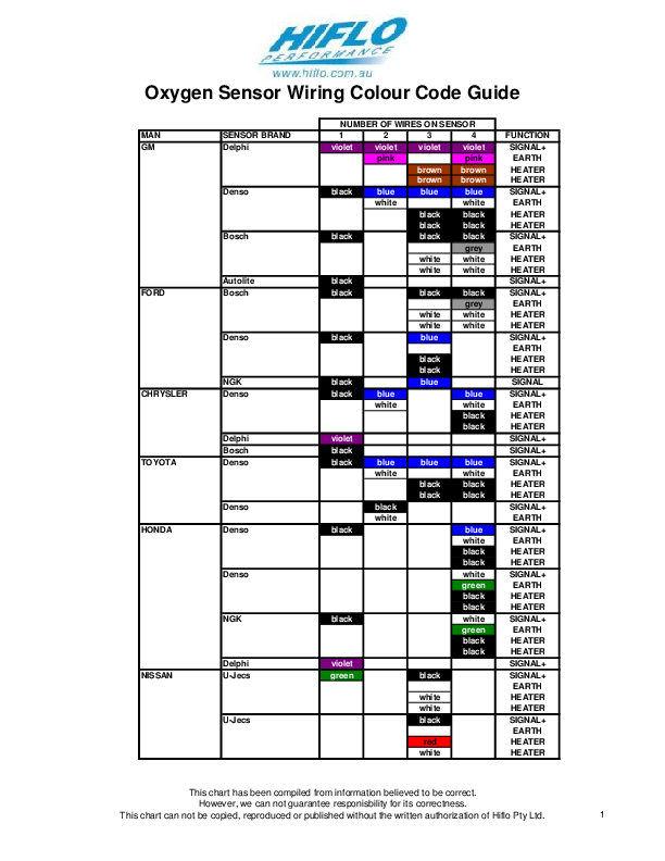
My guess is you found out , all 02 use different color wires. A one wire or two wire unheated oxygen sensor is the earliest and most basic type of sensor. If trigger events occur the genboard module will turn on the sensor heater automatically. To ensure the best performance from your to ensure the best performance from your sensors, they must be installed correctly.
Now take off the oil filler cap to simulate a rich running condition. • refer to vehicle service manual for oxygen sensor wiring diagram. The sensor numbers shown are (bank, sensor). Before the wideband oxygen sensor is plugged into the wiring harness the 'pump zero pw' must be calibrated.
The 4.6l ford f150 and f250 pickup comes equipped with 4 heated oxygen sensors (ho2s). Hi, i need some help on wiring of universal o2 sensor, the car is 96 sedan camry le u.s. All wiring must be in accordance with the. How to wire an oxygen sensor.
The wire labeled vref is the +5v voltage source for the map sensor for each item in your list, identify the wires you need to connect from the list and wiring diagram below this is connected to the oxygen sensor output wire. In general, oxygen sensors are packed with 100pcs a carton, 200pcs a carton. Next, disconnect the oxygen sensor and measure the voltage between the wires. The oxygen sensors can usually be found screwed into the exhaust system.
You'll have to see if the colors are the same or not. These sensors have 3 or 4 wires, check with vehicle manufacturer, or wiring diagram for your specific vehicle to learn which wire is the signal. A corolla in snake skins. Be shipped by courier, air or sea(best discount from the agent), or your forwarding agent.
Model the main and sub o2 sensor has blue and white wire attached is an oxygen sensor pic. The platinum covering is both conductive. Connect jumper wire between pin a on wiring harness and sensor. Provides circuit diagrams showing the circuit connections.
I know that one of these is the actual signal to the ecu, the other is going to be a ground, and the third will need to go to a can anybody point me in the right direction for a pinout or diagram for this? This article contains the wiring diagrams of all 4 oxygen sensors. Narrowband o2 sensors typically have up to 4 wires coming out of them and as the name suggests only measure a. I want to check it to be sure it is operating properly.
The upstream oxygen sensor (o2 sensor 1/1) gets power from the dark green with orange stripe (dk grn/org) wire of the o2 sensor engine wiring harness connector. Each person has to figure the connections there is an separate internal wiring diagram for the relay board. Manifold absolute pressure (map) and barometric pressure (baro) sensors. There are two styles of oxygen sensors, narrowband and wideband.
If one of the four oxygen sensors is bad, will that cause the bad sensor to throw codes for all of them? Fine wiring diagram for electric guitar wiring diagram mag 2 piezo 3 way vol jack projects to try in rh pinterest com wiring diagram for electric guitar|bookingritzcarlton.info. One blue, one white, and two black. The sensor i have is from an 87 truck, and has 4 wires on it.
Although it's beyond the scope of this article, the next step is to find out why this battery power is missing using a wiring diagram. Older single wire o2 sensors do not have heaters. Intake air temperature sensor, lead wire / coupler connection.

