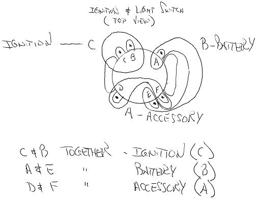
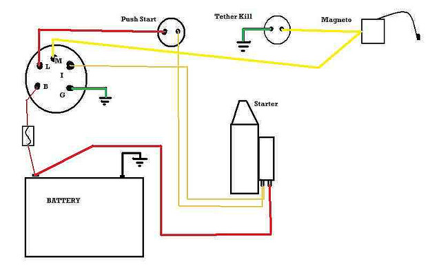
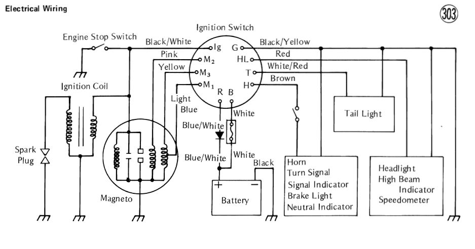
5 Pin Starter Switch Wiring Diagram
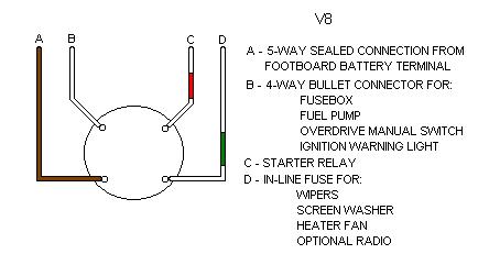
There are 6 wires , purple/white , 2 light green ,yellow , pink and a black/white.
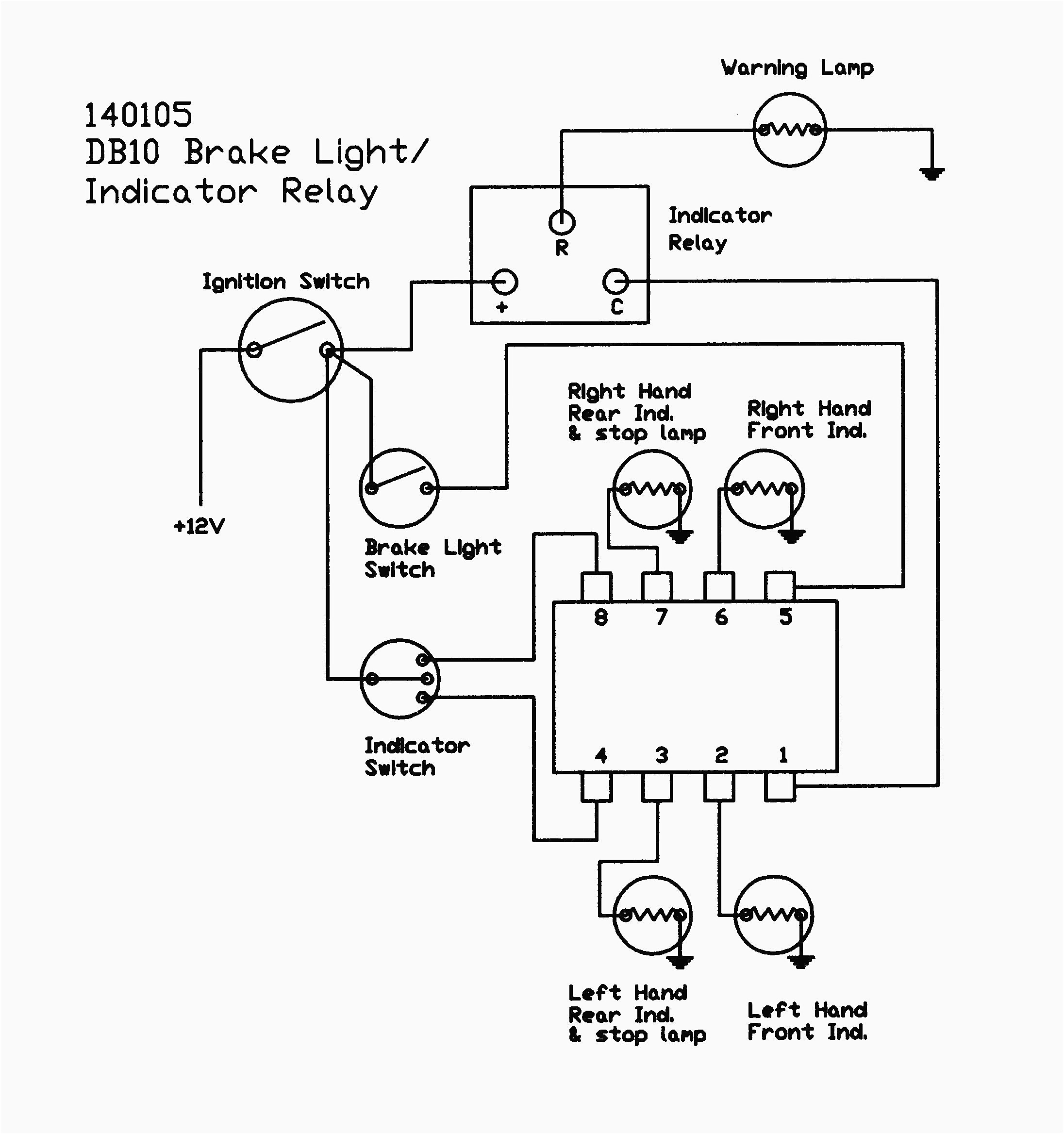
5 pin starter switch wiring diagram. The given circuit is a basic switchboard wiring for a light switch (one lamp controlled by one switch) and 3 pin plug socket with control switch. Pin #30 is the common switch; Here in this video you will learn how car starting system works. If you need help on this, see the youtube video;
Starting system & wiring diagram amazon printed books www.createspace.com/3623931 amazon kindle edition. The diagram doesn't differentiate between white and silver, so i'm not sure which one to solder to the. Helimech episode 25 or visit the button programming. I am trying to figure out what wires are what on my 95 integras ignition switch.
The brake switch keeps the quad from being started up accidently in gear. How a car starting system works: Any help would be appreciated ! 446 series relay harness wiring diagram.
I'm looking for a wiring diagram or just a list of what wire goes where on the big connector on the pnp switch. I found that removing the power switch, pluging it in, and then splicing the case power switch into the wires for that one is best. Check if you vehicle is negative switched: Nothing happens when i press it.
Omron ly23 ac model terminals/ back to front: Switch box wiring or switchboard wiring is a common wiring arrangement used in most house electrical wirings or switchboards. I don't know about a more durable version of this switch but the ibanez one is a 3ps1sc5 switch. Once the wiring is completed, its straight over to programming mobiflight and prosim.
I did some preliminary digging to find a compatible wiring diagram for the switch but cannot find the voltage/amperage settings for the switch's integrated led. A double pole, double throw switch is used for this purpose but you have to wire it up correctly t… i've had a number of people ask me about a wiring diagram, as the photos may not be enough on their own. The other pins (pin1 & pin2) in the diagram can be connected to any other pin on the arduino mega; How to wire an effect circuit into your guitar the humbucker has red, white, silver, green, and black wires coming from it.
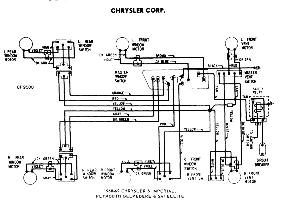
You will know how car self starter gets power and spins the engine. 5 pin power window switch wiring diagram power window main panel diagram driver and passengers switches power window wiring. Internally this reset pin is the reset pin of the sr flip flop and hence the output of 555 timer is a low logic signal. We have a variety of switches, rocker switches, toggle switches and more.
This causes the output of the 555 timer to have you used the same circuit diagram for implementing it practically? Wiring diagram nintendo switch wired controller street light wiring diagram vehicle wiring diagrams usa tunnel lighting wiring diagram garden lighting wiring quality assurance momentary carling lighted 5 terminals 5 pin rocker switch wiring diagram. The schematic diagram shows that with the motor operating. Black anti vandal toggle switch.
Sounds like you may be having multiple problems. System diagram, starter motor, solenoid, starter relay, neutral safety switch. Ensure your headlights are in the off position. Start date oct 18, 2018.
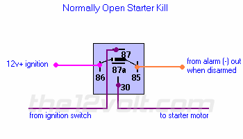
0x75 (read), 0x74 (write) lcd chip: Updated ats circuit diagram with complete ic 4060 and ic 555 wiring details. Pin #86 is for the 12 volt positive lead, and pin electric fan wiring diagram: Wiring diagrams do not show the operating mechanism since it is not electrically controlled.
O.e style switch wiring diagram. I just spliced the 5 pin wire back together and used the old button. Below you'll find a basic on/off rocker switch wiring diagram as well as an easy to understand illuminated rocker switch wiring diagram so no matter what your. Getting frustrated and 100 degree days aren't helping.
Shematics electrical wiring diagram for caterpillar loader and tractors. Rel2 activation switches on the 555 astable which starts counting upto 5 seconds and triggers t4/rel3 so that the generator starter motor begins cranking the gen. Start date oct 17, 2018. When switch s1 is at position 2, trigger pin of 555 timer is grounded.
There are 5 wires coming out of it, im trying to figure out which ones may be white is 12v+ input, [hot at all times] black/white is starter, [hot during cranking to start]. How would you wire a 7pin lighted dpdt switch for this same project? Trailer wiring diagram electrical circuit diagram motorcycle wiring jeep electrical projects mechanical engineering diy electronics automobile toyota. In your lifan diagram posted earlier i see only a four pin cdi, yet you report a five pin the starter solenoid wiring is unclear at best according to the diagram.
When wiring an electric fan, make sure the positive ignition lead is one that turns off when the starter is engaged. Starting system & wiring diagram amazon printed books www.createspace.com/3623931 amazon kindle edition. You can just wire across the brake switch part and then there will be no safety interlock. Do you think it is wire running from starter to ignition switch?
Chrysler wiring diagrams are designed to provide information regarding the vehicles wiring content.


