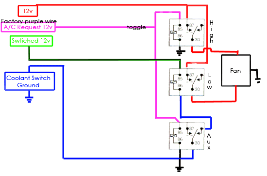
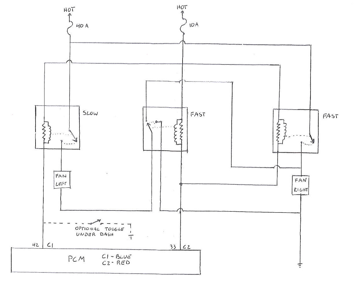
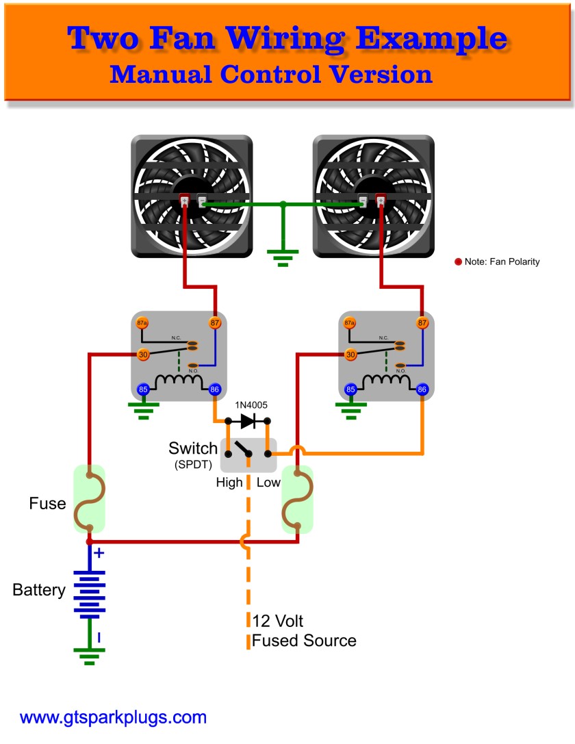
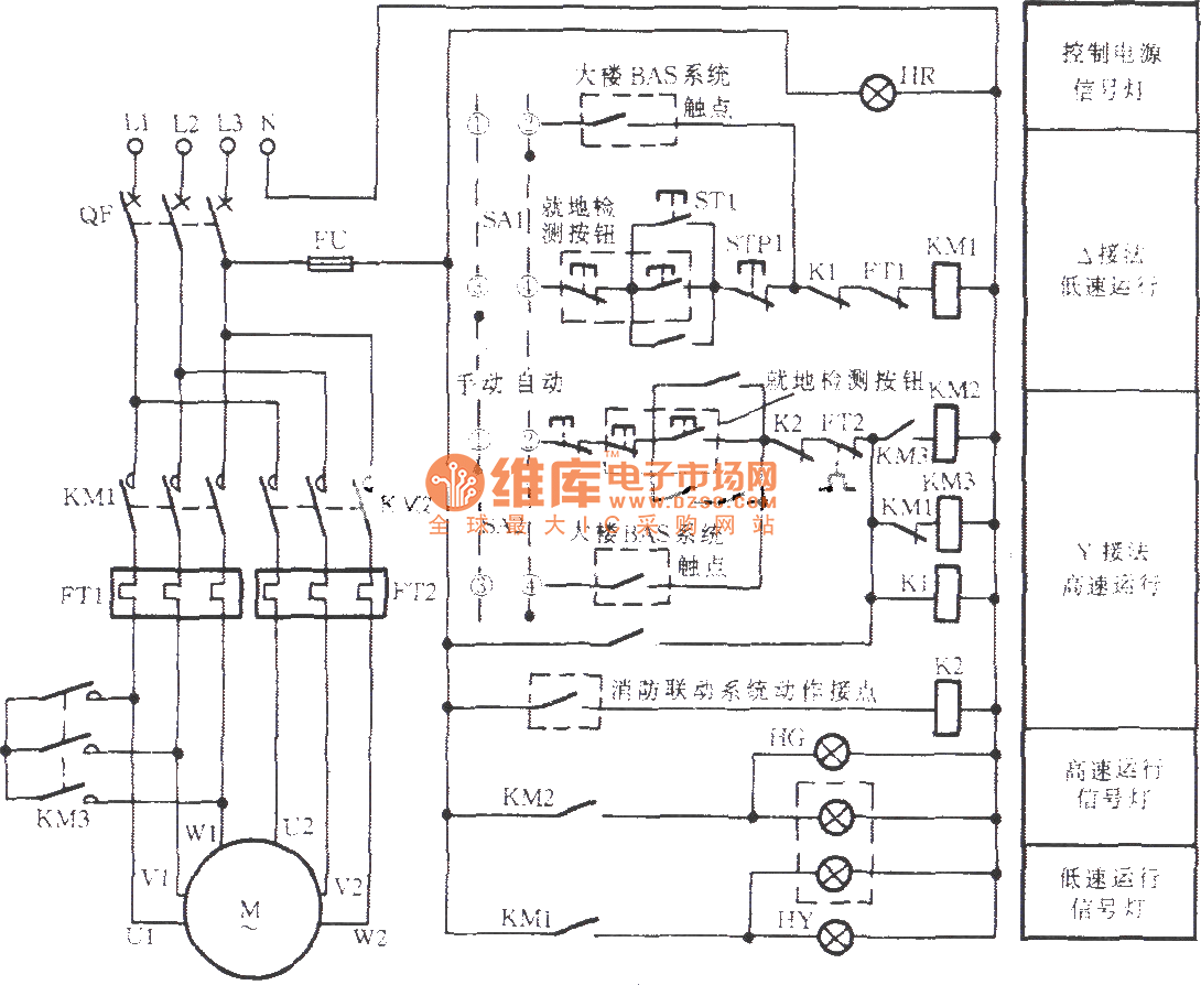
2 Speed Fan Motor Wiring Diagram
The duty cycle describes the amount of time the signal is in a high (on) state as a percentage of the total time of it.
2 speed fan motor wiring diagram. I found a discrepancy between the diagrams of the main 2 similar images and the small one #4 image. Running a fan slower reduces the. The existing wiring on the machine is not really any help, as the previous owner bypassed the. Closely examine the connector for corrosion or damage.
Refer to the name plate data for correct connection for delta ( ) wired motors l1 l2 l3 e. See more ideas about fan motor, diagram, thermostat wiring. Electric motor wire marking & connections. Using this fan speed controller circuit you can control the speed of 12v dc fans used in cars.
For example, when the motor of the drill machine is slowed down by the 1. Wiring of contacts and relays. The first motor control diagram can be much simplified by using a dpdt switch for the motor reversal operation, and by using an emitter follower transistor for the speed control you dont perhaps have a circuit for a 4 wire 48v dc fan, or can i just connect pin 7 directly to the yellow pwm controle wire? Electric motor run speed side you can also obtain a wiring diagram for your air handler brand, model, serial number from the manufacturer, or give us that information and we'll help.
Data on the motor for wiring diagrams on standard frame ex e, ex d etc. I hope to use the sc to slow down a fan 45 watts, may i use the ordinary 2. In basic diagram, there are four wires that connect to the motor: Find solutions to your 2 speed fan motor switch wiring diagram question.
However, in recent years, the technology of speed control—one way to answer some of these objections to the use of a fan—can have these advantages: In dahlander connection (tapped winding). Checking wires, connectors and related components. The top countries of supplier is china, from.
The circuit is built around timer 555, which is wired as an astable multivibrator. Fan motor driving circuit shown as a simple fan motor driving circuit, which is mainly from the power circuit fan power equipment traditional control methods is through manual or relay control, there is the problem. Additionally, some motors have more than one speed and will need to be wired properly to achieve the proper speed for the control settings. The circuit diagram of dc fan motor speed controller regulator circuit using 555.
The replacement switch has a pair of connections at each position; Motor wiring with cooling fan motor (f) or thermal protector (tp). 220vac motor speed controller schematic. Following is the schematic diagram of a dc motor, connected to the arduino board.
• the motor speed can be adjusted from the speed setting knob on the controller this wiring diagram causes the motor to rotate clockwise when viewed from the motor shaft end. See how to install & wire up an air conditioner compressor, blower motor, or fan motor hard starting capacitor. 2 speed cooling fan wiring diagram another impression: The problem now is how do we know which color usually the black wire is the common wire and we need this black wire as a reference to find out the different speed in term of ohm value.
I managed to get a new fan motor from local market. We are a team of ase certified mechanics that have created this guide to help replace a burned out blower motor and if there is no power on any of the lower speeds the resistor has failed and needs replacement. Compact electrical fans are cheap and have been used for cooling electronic equipment for more than half a century. Function of the ?circuit diagram:
The thermal protector (tp) is an. Unplug the fan wiring connector. How to test the cooling fan motor. The wiring for the heat pump condenser fan motor will be slightly different.
Pwm, or pulse width modulation is a technique which allows us to adjust the average value of the voltage that's going to the so depending on the size of the motor, we can simply connect an arduino pwm output to the base of transistor or the gate of a mosfet and control. The fan motor was checked and found that the coil was burnt. Fan motor exhaust fan motor dc motor fan 220v small electric fan motor fan motor 100w ceiling fan there are 14 suppliers who sells ac fan motor wiring diagram on alibaba.com, mainly located in asia. The dc motor will spin with different speeds according to the value (0 to 250) received via the 1 × arduino uno.
Here at speedway motors we're happy to help you understand the process. Fan now only runs on two speeds, need wiring diagram please i ran into this when replacing the 3 spd switch. 3ø wiring diagrams diagram dd1. Dual electric fans have several benefits, like being able to pull more cfm between the two fans versus having just.
Use our dual fan wiring diagram and guide to make sure you properly wire your fans to your thermostat. These diagrams are current at the time of publication, check the wiring diagram supplied with the. Can anyone refer me to a wiring diagram of the guts of this motor? Capacitor c1 is connected in parallel to the fan to stabilize its speed.
Related searches for ac fan motor wiring diagram: 3ø wiring diagrams diagram dd3. I'm having a hard time figuring out whats going on in there just from resistances. Wiring diagram for two speed attic fan switch | … перевести эту страницу.
The fan is not turning on low speed if the engine is on, even if it reaches the heat indicated. Inside all motors are coils of wire call windings. The black wire (noted in the wiring diagram) will likely be terminated on a control. Fan blower motor not working?


