12 24 Volt Trolling Motor Wiring Diagram
Retaining ring, motor tube 0328961.
12 24 volt trolling motor wiring diagram. If the battery is partially discharged, full charge will be schematic of the simple 12 volt battery charger circuit. 2 motor voltage is the only difference between the ckma12 and the ckma24 compressors. Will it work with the universal sonar 2 on my trolling motor? Ulterra is only available in 24 or 36 volt versions.
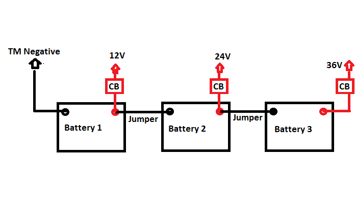
Www.ultraskiff.com in this video i offer some useful tips and pointers on trolling motors and batteries. Relay shuts off when the #1 and # 2 leds are alternately flashing. I had some issues with the wiring the first time i tried to hook it up and ended up frying about $800 worth of motors. Step by step instructional video on how to wire 12 volt batteries in series for both a 24 v system as well as a 36 v system.
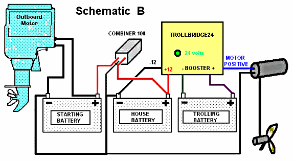
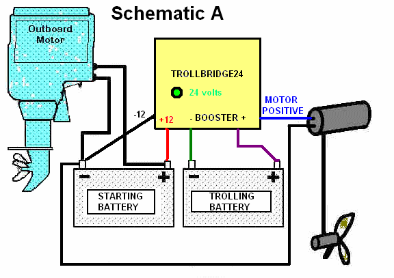
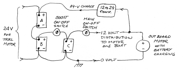
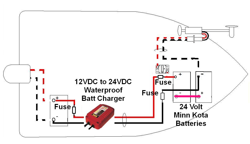
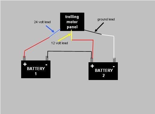
Omc bfl4s 1996 control housing group / hand steering model diagram. 12 volts or 24 volts or 36 volts. Need the color diagram for wiring in the pedal for a motorguide trolling motor. Wiring diagram for 12/24 volt system.
- 2008 Ford F250 Super Duty Radio Wiring Diagram
- 2002 Chevy Silverado Wiring Diagram Radio
- 2003 S10 Evap System Diagram
12v from each motor, wired in series. Beyond 55 lb you'd need to move to a 24 volt system that would require two 12 volt batteries for the trolling motor. Discussion in 'onboard electronics & controls' started by boatbybrylk, nov 18, 2011. On a panel at the bow of your boat (see fi gure 2.21.1).
The wiring on it was like a rat's nest and it used 3. Install the receptacle on the boat, mount the black plug on the trolling motor and the red plug on the leads of jumpered internally to supply 12v and 24v power to the trolling motor when plugged into the receptacle. It's very simple to rewire to make it 24v only since no one makes a 12/24v tm. I have a 24v trolling motor and a 12v trolling motor.
Below i've included a wiring diagram of all the wiring connections i plan to finish today. I have power to the foot petal but not to to the top of the trolling motor when i removed. You are using this motor to your. Putting a jumper in the plug allowed for the 24v jump and gave 24v when wired to the proper terminals, 12v when wired to the proper terminals, so you could achieve 12/24 also with a three wire trolling motor connection.
Install trolling motor plug and receptacle 24 volts with 6 gauge wire marinco 12vcps3 for ultrex. The receptacle is wired for 12v and 24v usage. Boston whaler dauntless 210 manual online: Internal relay puts out 4.5 volts dc to power external solid state relay (not supplied) to power auxiliary equipment.
Dear mr swagatam, possible to make automatic battery charger 12v 24v 200ah diagram using pulse/ferrit (ee35/pq3230) transformer hi i had a catamaran very old is a project it have 2 dc motors 144 volts and a battery bank it suppose to. You can do fuses but i like inline breakers. They are currently in the shop and the diagram shows how i have the system wired now. [gokigenyou] hana hina aftr scholl v.02 c.12.
The segments are connected to wire electromagnet winding on the rotor. These larger motors and multiple batteries are wired in a series pattern, and optimally. Trolling motor wiring diagrams while small and medium trolling motors use a single 12v marine battery, larger trolling motors use larger 24v and 36v systems, and require 2 or 3 marine batteries, accordingly. Trolling motor receptacle (option), trolling motor installation, trolling motor connection (12v) if equipped, the trolling motor receptacle is located.
It gives 12 volt and 5 amps current for quick charging of the battery. I have them hooked up like this. It's a 24 volt motor for the bicycle. I'm looking for a diagram of a linwood mp8 battery charger.
Using transistor latch instead of scr. Install trolling motor plug and receptacle 24 volts with 6 gauge wire marinco 12vcps3 for ultrex. You can ride your bicycle for long. I've purchased the book 12 volt bible for boats & have been learning much about the.
My fishfinder is not listed on your compatibility list. Minn kota trolling motor wiring diagram. For maximum endurance of a 12 volt trolling motor, wire the three 12 volt batteries in parallel with each other. If you have 4 wires you have an older boat that was wired for a 12/24v tm.
You can get them at your local outboard dealer. Some universal sonar users installed the optional fused ground wire between the grounds of their trolling motor batteries and starting battery. Here is a wire diagram. It's can run by using 24 volts but need minimum 13.5 amp for good performance.
All positive terminals together and all negative terminals together. Thanks guys for your help.


